| “This site contains affiliate links for which OEMDTC may be compensated” |
NHTSA ID Number: 10144463
Manufacturer Communication Number: PIT5473E
Summary
This Preliminary Information communication provides information to the technician about vehicles that have “ADAPTIVE CRUISE TEMPORARILY UNAVAILABLE” message on the Driver Information Center when attempting to activate the cruise. Technician should consider environmental factors, repair, collision, aftermarket parts, and radar alignment factors. For Cadillac Escalades model years 2015-2017 in a barren environment, technician will need to update the Long Range Radar module with the latest software available in Tis-2-Web.
5 Affected Products
Vehicle
CADILLAC | ESCALADE | 2015-2019 |
SEOCONTENT-START
Bulletin No.: PIT5473E
Published date: 08/20/2018
Preliminary Information
PIT5473E Diagnostic Tip – Adaptive Cruise Temporarily Unavailable and/or Service Driver Assist Message
Models
| Brand: | Model: | Model Years: | VIN: | Engine: | Transmissions: | |
|---|---|---|---|---|---|---|
| from | to | |||||
Cadillac |
Escalade | 2015 – 2019 | All *See Note | All *See Note | All | All |
*With Driver Assist Package (RPO Y66)
Supersession Statement:
This PI was superseded to add the 2019 models and update the Title, Condition/Concern and Recommendation sections. Please discard PIT5473D.
The following diagnosis might be helpful if the vehicle exhibits the symptom(s) described in this PI
Condition / Concern
A customer may comment they receive an “ADAPTIVE CRUISE TEMPORARILY UNAVAILABLE” message on the DIC when attempting to activate the cruise. In some cases, a “Service Driver Assist” message maybe displayed when the vehicle is started.
The active safety control module provides the adaptive cruise control system functionality. The active safety control module analyzes data from the long range radar sensor module, front short range radar sensor modules, and front view camera module to identify and classify objects in the road environment. If any of the radars or the camera becomes blocked or misaligned, an “ADAPTIVE CRUISE TEMPORARILY UNAVAILABLE” and/or “SERVICE DRIVER ASSIST” message may be displayed and the adaptive cruise will be disabled.
Recommendations / Instructions
Note: This document is only to provide additional tips when diagnosing an “ADAPTIVE CRUISE TEMPORARILY UNAVAILABLE” and/or “SERVICE DRIVER ASSIST” message and is not meant to be a diagnostic flow chart or replace SI. As always, refer to SI for the latest diagnostic information and procedures.
The following items should be considered when diagnosing an “ADAPTIVE CRUISE TEMPORARILY UNAVAILABLE” and/or “SERVICE DRIVER ASSIST” message.
1. Aftermarket Equipment
Visually inspect the vehicle for any aftermarket add on equipment like bug deflectors, windshield tint/banners, grille emblems, push bars, license plates, etc. These items could block the radar / camera’s view. Question the customer to see if this concern started after the installation of the aftermarket equipment. Remove any aftermarket items and retest system for proper operation.
2. GDS Diagnostics
2.1 It is imperative to use GDS and do a Complete Vehicle DTC check. There are subsystems which are used by the adaptive cruise control system that may not seem to be related, but, are in fact needed.
For example, the parking brake system is used during extended stops after the adaptive cruise control system has already brought the vehicle to a complete stop using the vehicle’s service brakes. If the parking brake system has an issue or has a code set, the adaptive cruise may be unavailable. In this instance, the parking brake system’s issue will need to be addressed first.
2.2 If no DTC’s are found, use GDS and review the following data in the Active Safety Module and ECM:
Active Safety Module – “Adaptive Cruise Control Inhibit History Data 1-6” and “Adaptive
Cruise Control Disengage History Data 1-6″
ECM – “Cruise Control Disengage History 1-8”
This data can be used as a tool to help pinpoint the reason why the adaptive cruise is unavailable. Follow the appropriate SI diagnostics for any of the inhibit or disengage reasons that are indicating an incorrect value and correct them first.
Diagnostic Tips for “Disengage History Data – Loss Communication With The Active Safety Control Module” showing as “Yes”:
– Use GDS and go into the Long Range Radar Module -> Data Display -> view parameter “Long Range Radar Sensor Module Blocked”. When the concern duplicates, if this parameter shows “Yes” it could be caused by any of the issues listed in Steps 1 or 3.
3. Radar(s) and/or Front Camera Detecting a Blockage
A blockage can be caused by a number of reasons; following are some examples:
3.1 Environmental Reasons
3.2 Long Range Radar / Camera Improperly Mounted or Misalignment
3.3 Repair/Collision/Aftermarket/Wrong Parts
The radars and front camera are continuously monitoring for a blocked condition and if it determines its ability to “see” clearly is compromised, the radar/camera may become unavailable. When this occurs, the cruise will disengage and/or no cruise engagement with an “Adaptive Cruise Temporarily Unavailable” message. Since the radars cannot visually “see” they rely on a complex blockage detection algorithm to predict blockage. Also, keep in mind that the front camera cannot see through objects or debris, so the camera can become visibly blocked. It is important to understand that disabling the adaptive cruise control, as a result of sensor blockage, is a normal function of the system and is intended to protect the driver from compromised system performance. Blockage detection is needed because if the radars/camera were/was truly blocked, the adaptive cruise control would not function properly.
3.1 Environmental Reasons
- Foul weather: Foul weather such as snow, ice, heavy rain, road spray conditions may limitthe sensors ability to “see”. Also, a buildup of mud, snow, frost, dirt, bugs, etc on the windshield or front fascia can cause a blockage. This buildup can also occur on the back side of the fascia between the radar and back of fascia. One example, if the windshield has a buildup of frost/snow/ice which covers the front camera, the system may detect a blockage and disable the cruise. After the defroster warms the windshield and melts away the frost/snow/ice the system will become operational. This example may appear to be an intermittent issue.
Note: If driving in 4WD HI range, adaptive cruise control will be disabled, which is normal. (Adaptive cruise control will function in Auto 4WD.)
- Dark Rural Areas: In very dark rural areas, the front view camera may detect blockage.
- Very High Ambient Temperatures: Very high ambient temperatures may affect camera operation. (Normally only seen in areas in the Southwest United States where outside temperature may reach in excess of 100° F) See the latest version of PIC6123 for more information.
- Barren Environments: As part of the blockage detection algorithm, the radar may conclude it is blocked if the radar does not “see” anything over a period of time. This can happen when driving in very bare environments, such as deserts and rural areas where there are no large objects to detect like other vehicles, bridges, building, trees, signs, mail boxes, guard rails, etc. Below is an example photo of an area where the radar may determine a blockage because there are no objects in the environment for the radar to “see”. In these cases, if the system does not detect an object within approximately 60 seconds or 1.2 miles (2 km) the cruise will be disengaged and a “ADAPTIVE CRUISE TEMPORARILY UNAVAILABLE” message. If there were other vehicles on the road for the radar to detect there would not be any issues. Because of this, it may appear to be an intermittent concern to the customer, and difficult for a dealership to duplicate.
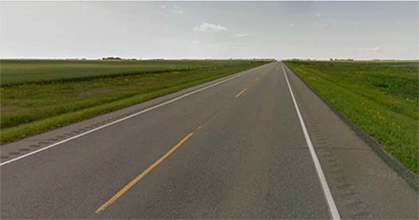
If a blockage is detected by any one of the above environmental reasons, it is not a latched condition, meaning once the radar/camera viewing area is cleared and/or the environment allows the radar to “see” both moving and stationary objects, the system will become available again without cycling the ignition off and back on. The driver should attempt to reengage the system after a several minutes of driving once the viewing area is cleared or objects (other vehicles, bridges, etc.) are now in the environment.
Note: For the long range radar to unlatch and become functional again it needs to “see” both moving and stationary objects. In some very rural areas, it may be several miles (2030miles) of driving before both types of objects are available for the radar to “see”. Stationary objects like road signs, mail boxes, guard radar, need to be close enough to the side of the road to be detected. Some areas have road signs set far off the side of the road and cannot be detected.
- Update for Barren Environment: The Long Range Radar (LRR) Module software has been updated to address barren environment performance concerns for the 2015/16/17 Escalade models. Reprogram the LRR module with the latest software available in TIS2WEB.
3.2 Long Range Radar / Front Camera Improperly Mounted or Misalignment
If the long range radar and/or front camera is improperly mounted or misaligned, they may not be able to “see” objects and determine there is a blockage, which will disable the cruise.
- Suspension Trim Heights: Incorrect suspension trim heights: Inspect for aftermarket lift kits or leveling kits, air suspension or spring issues. Any of these issues may change what the radar/front camera can detect and affect the operation of the system. Refer to the latest version of PIT5403 for additional information.
- Camera Mounting: Inspect the front view camera sensor, on the windshield near the inside rearview mirror, to make sure it is attached properly to the windshield.
- Radar Mounting / Alignment: Inspect the long range radar for proper mounting/alignment. In most cases, a mounting/alignment issue may be caused by a front end impact/collision that may or may not be obvious. Many of the new materials that the front grilles, fascia, and lower air dams are made with are very resilient. If they are hit with mild to moderate force, they will bounce back with little, if any noticeable damage. However, the long range radar or the radar bracket behind the grille, fascia, or lower air dams may be damaged/bent/misaligned, even though no obvious damage may be seen on the outside of the vehicle. Reports of the Long Range Radar Module bracket being bent have been received and it is suspected to occur while parking and contacting a snow bank, parking curb or similar object.
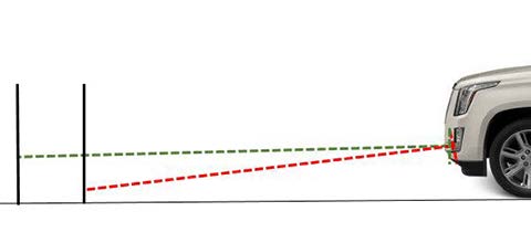
The Long Range Radar Module is scanning for objects up to 656 ft (200 m) in front of the vehicle as represented by the green line in the illustration below. Even the slightest bend in the radar bracket will cause the radar not to be able to “see” objects farther out from the vehicle as represented by the red line in the illustration below. If the Long Range Radar cannot “see” objects throughout the full range of 656 ft (200 m), it will determine the radar is blocked and disable the cruise along with the GDS relearn procedure will not complete, or it may fail or error out when it is performed. DTC B101E 4B can set if the radar cannot “see” objects throughout the full range of 656 ft (200 m) when performing a learn.
GDS can be used to review the Misaligned-Angled data in the Long Range Radar Sensor Module by going into Module Diagnostic>Long Range Radar Sensor Module>Data Display (see note below). There are 4 angled parameters to review: Up, Down, Left, and Right. If any of the parameters show “Yes” this is a good indication the long range radar is misaligned and that the alignment needs to be checked / learn procedure performed.
Note: Using GDS to check the long range radar Misaligned-Angle data may not always indicate a radar that is or is not aligned properly. Always perform the physical alignment check below.
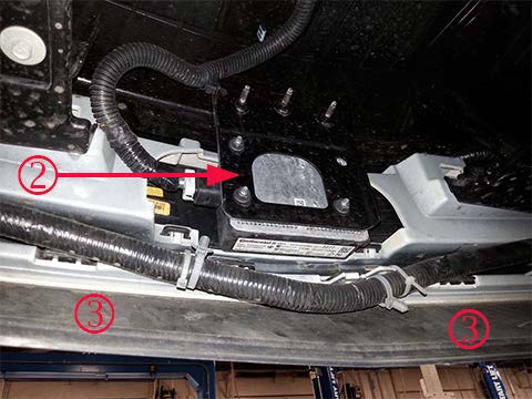
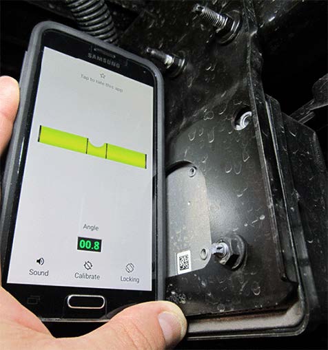
– Radar Bracket Inspection: Physically check the Long Range Radar Module bracket (2) to make sure it is in alignment. Place the truck on an alignment rack to ensure a flat, level surface. Use an angle gauge/level to make sure the bracket is mounted 90 degrees (+/- 3 degrees) to the level alignment rack. Position a digital angle gauge/level on the long range radar bracket behind the module and check the vertical alignment, as shown below. The Long Range Radar Module must be mounted straight up and down vertically +/- 3 degrees. If misaligned, the Long Range Radar Module bracket is not adjustable and the mounting bracket is most likely bent and will need to be replaced.
After the Long Range Radar Module alignment has been checked and/or corrected, perform the Long Range Radar Learn in GDS by following the Radar Sensor Module – Long Range Programming and Setup procedure in Service Information.
NOTE: Early built 2015 models (early built 2015 models can be determined by NOT having RPO AVF) had the long range radar mounted higher, behind the Cadillac emblem in the grille (not shown).
3.3 Repair/Collision/Aftermarket/Wrong Parts
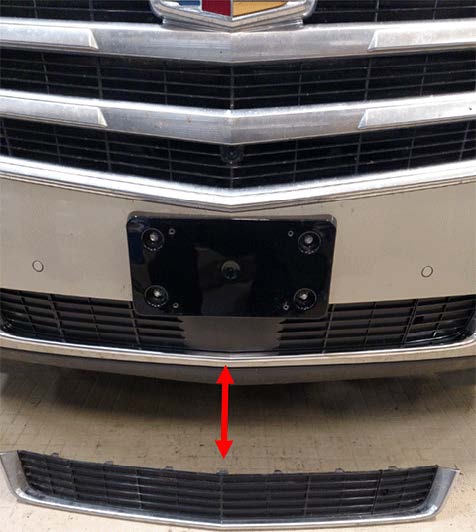
– Beware of any front end parts that may have been replaced with the wrong OEM part, aftermarket part, etc. In many cases, after a front end repair is done, if the wrong or certain aftermarket parts are used, they may block or misalign the radars or camera.
Below is an example of the wrong OEM front lower grille molding that was installed (2). The long range radar module is located behind the lower grille molding. The wrong lower grille molding (the one on the floor item 2) had been installed on this vehicle. The long range radar module could not “see” through the molding correctly and would detect a blockage and disable the cruise. The correct lower grille molding (the one shown on the truck item 1) was installed on the truck, which corrected the concern.
Warranty Information
The correction may involve one of several different repairs.
For vehicles repaired under warranty, please use the appropriate warranty labor operation based on the actual cause and repair.
For 2015/16/17 Vehicles Only – to Address Barren Environment Performance in Step 3.1, use;
| Labor Operation | Description | Labor Time |
| 2810645 | Radar Sensor Module – Long Range Reprogramming with SPS | Use Published Labor Operation Time |
Please follow this diagnostic or repair process thoroughly and complete each step. If the condition exhibited is resolved without completing every step, the remaining steps do not need to be performed.
SEOCONTENT-END
Bulletin No.: PIT5473E
Published date: 08/20/2018
To View or Download this Document Click Here
Bulletin No.: PIT5473D
Published date: 11/21/2017
To View or Download this Document Click Here
Bulletin No.: PIT5473C
Date: Dec-2016
To View or Download this Document Click Here
Bulletin No.: PIT5473B
Date: Sep-2016
To View or Download this Document Click Here
Bulletin No.: PIT5473A
Date: Apr-2016
To View or Download this Document Click Here
PIT5473A
To View or Download this Document Click Here
Bulletin No.: PIT5473
Date: Oct-2015
To View or Download this Document Click Here
Reprogramming
GM Diagnostic/Programming (TIS2Web)
Approved J2534 Device with TIS2WEB can reprogram 1996 and later All GM Modules.
To obtain the latest electronic controller calibration information for your vehicle, go to https://tis2web.service.gm.com/tis2web and enter the vehicle's 17 character Vehicle Identification Number (VIN) and select 'Get CAL ID’.
You can then compare the latest part number with the actual number installed on the vehicle to determine if a reprogram is needed.
The Service Programming System (SPS) application is part of the TIS2Web system. To program an ECU, the SPS application must communicate with the vehicle control modules using the proper J2534 programming interface tool.
The following are the supported interface tools:
The Tech 2 supports model years 1996 and beyond. With the addition of the CAN Diagnostic Interface (CANdi) module, Tech 2 is fully backward compatible with current Tech 2 functionality and operates transparently when diagnosing non-CAN-equipped vehicles.
Servicing the next generation Global A vehicles will require the diagnostic software, GDS2, Global Diagnostic System 2 running on a local PC device while the MDI is connected to the vehicle. The GM MDI is the Global Diagnostic tool for future vehicles starting with Global A vehicles.
The GM MDI was introduced in the fall of 2007 for Pass-Thru programming and offers faster programming speed. It can be used to perform Pass-Thru programming on all vehicles built since 1996 and into the future. Click here to view a list of GDS supported vehicles.
- J2534 Pass-Thru Programmer: TOPDON RLink J2534 is an advanced diagnostic and reprogramming tool that support all J2534 protocols, as well as D-PDU, CAN-FD and DoIP, ensuring compatibility with a wide range of modern vehicles. It offers extensive versatility with support for over 17 major automotive brands, including Chrysler, Ford
 , GM, Nissan
 , Toyota
 , Honda, Subaru
 , Land Rover/Jaguar, Volvo, Wuling, Volkswagen, Mercedes-Benz, and BMW, and so on, enjoy dealership-level functions at your fingertips
 - All-in-One OEM Diagnostics: This J2534 ECU programming tool elevates your automotive repair capabilities to new heights by delivering complete OEM diagnosis. Boasting comprehensive full-system diagnostics, intuitive repair guides, advanced ECU programming and coding, common reset services, a vast library of repair information and more, this all-in-one solution empowers technicians to effortlessly tackle complex vehicle issues with ease
- Proven Performance You Can Trust: Backed by over 10000 real vehicle tests and benefit from a wealth of practical experience, this OEM reprogramming tool guarantees stable and exceptional performance. Supported by TOPDON's dedicated technical experts with in-depth knowledge of both auto repair and J2534 Pass-Thru programming, the RLink J2534 provides prompt and professional assistance, ensuring a smooth setup and reliable compatibility
- Integrated Excellence, Always Up-to-Date: Featuring the exclusive RLink Platform to provide a streamlined experience with one-click driver installation and management, ensuring flawless integration with your OE software, maintaining the original performance quality. The built-in operation guide makes mastering OE software quick and easy, so you can get started right away. Plus, with lifetime free updates, your diagnostics will stay current with the latest drivers and innovations
- Efficiency Meets Versatility: Engineered to support three CAN channels simultaneously - CAN FD and CAN-CC included, giving you the edge in fast troubleshooting. To perfectly synchronized with the OE software, please diagnose with active subscriptions and make sure your computer system is running a compatible 64-bit Windows version (7, 8, 10 or later) to fully leverage the power of RLink J2534. *We don't provide extra OE software
- 【J2534 PROTOCOL WITH SMARTLINKC】 LAUNCH X431 PRO3S+ ELITE scan tool with newly upgraded smartlinkC V2.0. The SmartLinkC is a communication interface supporting J2534 specifications. Of course, it also can be used as a J2534 PassThru device, working together with the PC installed with the OEM diagnostic software to perform the J2534 protocol.J2534 protocol is the only solution for problems ranging from driveability and loss of power to poor fuel economy.
- 【INTELLIGENT TOPOLOGY MAP TO FASTER FULL SYSTEMS DIAGNOSIS】 X431 PRO3S+ELITE bidirectional scan tool with new-added intuitive topology mapping. Harnesses intuitive topology mapping for comprehensive visualization of the vehicle all system. It shows all available control units in different colors, the numbers of system, the scanned system, and the scan results, bringing maximum convenience & superfast speed for you to do swift diagnosis & high-level repairs.
- 【TOP HARDWARE CONFIGURATION, UPGRADED OF LAUNCH X431 PRO3S+】 LAUNCH X431 PRO3S+ELITE diagnostic scanner possess with Android 10.0 OS; CPU 4-Core Processor, 2.0 GHz. Greatly increased the speed of running multiple task. 2.4GHz/5GHz; 6300mAh/7.6V stronger battery capacity; 10.1 Inch Touchscreen with 8MP camera; AUTO VIN; 4GB+64GB storage memory; 20X faster transmission rate, save more vehicle documents and customer data; Supports 25+ Software Languages, such as EN, DE, FR, SP nd JP and so on.
- 【3000+ ACTIVE TEST/BI-DIRECTIONAL CONTROL LAUNCH SCANNER】 LAUNCH X431 PRO3S+ELITE HD automotive scanner is a cost-effective bidirectional scanner that deserves owned by every repairing DIYers and mechanics. You can easily send command signal at fingertips from the scanner to various module actuators to test component integrity and functionality in minutes or even seconds to tell if replacement or repair is needed.
- 【COMPLETE 60+ HOT RESETS, CALIBRATION, INITIALIZATION, RELEARN】 LAUNCH X431 PRO3S+ELITE SmartLinkC escaner automotriz professional enjoys 60+ special service, such as Oil Reset, ABS brake bleed, EPB, SAS, BMS, Suspension, Injector reset, Power Balance, Turbo Calibration, VGT, Transmission Adaption, Throttle Adaptation, matching and etc. rigorous on-site testing has been performed to ensure 100% availability.
- 🌐【Works with Autel Elite II Elite MS908 MS908S Pro II MS908CV II MK908P MK908 Pro II】Autel J2534 work with these tools to program ECUs on specific BM.W/ BE.NZ for specific functions. ★★NOTE: J2534 CANNOT directly work with these single devices. After you received the J2534, you HAVE TO send us both the S/N(12 digits) of your scanner MS908S(etc.) and J2534. So, technically, Autel engineers can help you bind J2534 with your devices. If need any supports, contact us via: 🚘auteldirect @ outlook. com🚘.
- 🌐【SAE J2534-1 & J2534-2 Standards】Autel MaxiFlash Elite J2534 is a fully compliant SAE J2534-1 & SAE J2534-2 (March 2006) device, which performs standard PassThru J2534 functionality: Compatible with for Toyota
 Techstream, Volvo VIDA, Honda HDS, Jaguar-Land Rover IDS and BM.W 3G for OEM diagnostics. Autel MaxiFlash J2534 is also specially designed to provide users with P-C communication and ECU reprogramming capabilities on any modern vehicle diagnostic bus, reliability and flexibility.
 - 🌐【High-speed Transmission Speed】Autel MaxiFlash Elite Reprogramming Device J2534 supports simultaneous communication definition in J2534-1, running 3 protocols at the same time, which greatly improves reprogramming and diagnostic speed. Embedded with the ARM9 Dual-core processor (clocked up to 500MHz), which further boosts the communicating speed to save more times and win more business.
- 🌐【Multiple Devices Connected with P-C】Autel MaxiFlash Elite J2534 also supports multiple device connections to the P-C, which can operate diagnostic and reprogramming functions on more than one vehicle at the same time. Autel MaxiFlash Elite J2534 built-in wireless and data storage, which can update via Internet. It also ensures quickly reprogramming even the newest controllers.
- 🌐【Extensive Compatibility】Autel MaxiFlash J2534 is compatible with Toyota
 Techstream, Volvo VIDA, Honda HDS, Jaguar-Land Rover IDS and BM.W 3G for OEM diagnostics. To check compatibility, please contact 🚘auteldirect @ outlook . com🚘 directly for satisfaction-guaranteed support!
- ALL OF THE J2534 PROTOCOLS - This single unit has all of the protocols you need for your OEM J2534 reprogramming and diagnostics including the latest in DoIP and CanFD
- J2534 TECHNICAL SUPPORT - FREE for the life of the tool. Staffed by technicians who understand vehicle repair and J2534 Pass‑thru
- TOOLBOX WITH OEM APPLICATION DESCRIPTIONS - educational video tutorials and real-time news – Giving you the confidence and up-to-date knowledge to get the job done
- J2534 v05.00 API - The newest version of J2534 to give you the latest in pass-thru technology
- FUTURE PROOF WITH 4 CAN CHANNELS - Going beyond the 3 required by select Chrysler/FCA models, CarDAQ-Plus 3 also provides a 4th to meet the needs of future OEM applications
- CUSTOM-DESIGNED FOR USE WITH FORSCAN: Works with all FORScan compatible vehicles and is recommended by the FORScan Team
- DEALERSHIP-LEVEL DIAGNOSTICS: OBDLink EX supports all Ford
 protocols, modules, and advanced features of FORScan
 - ELECTRONIC SWITCH allows FORScan to access all CAN buses simultaneously and enables advanced functions not possible with “toggle switch” adapters
- MAXIMUM THROUGHPUT -- up to 20 times faster than “toggle switch” adapters
- ROCK-SOLID CONNECTION avoids data corruption and dropped packets
- [J2534 COMPLIANT] - The Mastertech II is a J2534-1 and J2534-2 compliant VCI for OEM reprogramming and diagnostic applications
- [FULLY VALIDATED BY TOP 6 OEMS] - Mastertech II has been fully validated to operate with the top 6 OEM reprogramming applications: GM, Ford
 , FCA, Nissan
 /Infinity, Honda/Acura, and Toyota
 /Lexus
- [PRE-CONFIGURED] - The pre-configured wireless and wired connections make it quick and easy to connect to a vehicle from your PC (requires PC compliant with OE specifications and software)
- [RIGHT TO REPAIR] - Supports 'Right to Repair' (R2R) initiatives
- [COMPREHENSIVE KIT] - Kit includes: VCI, WiFi adapters (wireless PC to VCI), J1962 Cable (connect to vehicle), USB cable (connect to PC for firmware updates and setup), and Quick Start Guide
Last update on 2025-05-08 / Affiliate links / Images from Amazon Product Advertising API
This product presentation was made with AAWP plugin.
