
| “This site contains affiliate links for which OEMDTC may be compensated” |
NHTSA ID Number: 10113715
Manufacturer Communication Number: 08-07-30-021H
Summary
This technical bulletin provides repair information to correct customer concerns of loss of high speed GMLAN communications, intermittent no crank, IP gauge fluctuation, intermittent door lock cycling /chime operation, various IP warning lamps illuminated, transmission may not shift, communication DTCs U0073, U0100, U0101, U0102, U0109, U0121 or U0140 set.
118 Affected Products
Vehicles
CADILLAC | ESCALADE | 2007-2014 |
| CADILLAC | ESCALADE ESV | 2007-2014 |
| CADILLAC | ESCALADE EXT | 2007-2013 |
| CADILLAC | XLR | 2007-2009 |
| CHEVROLET | AVALANCHE | 2007-2012 |
| CHEVROLET | CORVETTE | 2007-2014 |
| CHEVROLET | SILVERADO 1500 | 2007-2011 |
| CHEVROLET | SILVERADO 2500 | 2007-2014 |
| CHEVROLET | SILVERADO 3500 | 2013 |
| CHEVROLET | SUBURBAN | 2007-2014 |
| CHEVROLET | TAHOE | 2007-2014 |
| GMC | SIERRA 1500 | 2014 |
| GMC | SIERRA 2500 | 2007-2014 |
| GMC | SIERRA DENALI | 2007-2013 |
| GMC | YUKON | 2007-2014 |
| GMC | YUKON DENALI | 2007-2013 |
| GMC | YUKON DENALI XL | 2007-2013 |
| GMC | YUKON XL | 2007-2014 |
| HUMMER | H2 | 2008-2009 |
Parts
| J-38125 Terminal Repair Kit, Yazaki Tray Number 12 – Female Terminal | 22124472200 |
| RESISTOR – DATA LINK | 88988999 |
| Dielectric Lubricant (50 gram tube) | 12377900 |
| (in Canada) Dielectric Lubricant (50 gram tube) | 10953529 |
| Woven Polyester (PET) Electrical Tape | – |

SEOCONTENT-START
#08-07-30-021H: Loss of High Speed GMLAN Communications, Intermittent No Crank, IP Gauge Fluctuation, Intermittent Door Lock Cycling / Chime Operation, Various IP Warning Lamps Illuminated, Transmission May Not Shift, Communication DTCs U0073, U0100, U0101, U0102, U0109, U0121 or U0140 Set – (Jun 25, 2015) – 08-07-30-021G
| Subject: | Loss of High Speed GMLAN Communications, Intermittent No Crank, IP Gage Fluctuation, Intermittent Door Lock Cycling, Intermittent Chime Operation, Various IP Warning Lamps Illuminated, Transmission May Not Shift, Engine May Stall, Communication DTCs U0073, U0100, U0101, U0102, U0109, U0121 or U0140 Set (Repair Terminals in Transmission Harness Connector, Repair Open or Shorted GM High Speed LAN Circuits, Open or Shorted Data Link Resistor, Corrosion or Poor Connections in Various Control Module Connectors) |
| Models: | 2007-2009 Cadillac XLR |
| 2007-2014 Cadillac Escalade |
|
| 2009-2013 Cadillac Escalade Hybrid |
|
| 2007-2013 Chevrolet Avalanche, Silverado 1500 | |
| 2007-2014 Chevrolet Corvette, Silverado 2500/3500, Suburban, Tahoe |
|
| 2008-2013 Chevrolet Silverado Hybrid, Tahoe Hybrid | |
| 2007-2013 GMC Sierra 1500 | |
| 2007-2014 GMC Sierra 2500/3500, Yukon | |
| 2008-2013 GMC Sierra Hybrid, Yukon Hybrid | |
| 2008-2009 HUMMER H2 |
|
| Equipped With Gasoline Engine and 6 Speed Automatic Transmission 6L80 (RPO MYC) or 6L90 (RPO MYD) |
|
| Equipped With Hybrid Propulsion (RPO HP2) and Two Mode 2ML70 Automatic Transmission |
|
| Attention: | As of the 2015 calendar year, the Data Bus Diagnostic Tool is available to assist in diagnosing issues with High Speed LAN. Refer to the Data Bus Diagnostic Tool User Guide, available in SI under Select and View a User Guide on the base screen. If after using the Data Bus Diagnostic Tool, the cause of the issue has not been found, continue with this bulletin which covers common areas of possible concern. This also applies to any of the above models that may be Export vehicles. |
This Bulletin has been revised to add Model Years and update the information. Please discard Corporate Bulletin Number 08-07-30-021G.
Condition
Some customers may comment on any of the following conditions:
- The malfunction indicator lamp (MIL) may be illuminated.
- Instrument panel cluster (IPC) warning lamps may illuminate.
- The transmission may not shift or defaults to 2nd gear.
- The door locks may cycle by themselves.
- The engine may not crank intermittently.
- Engine may stall (applies to Corvette, Hybrid Full Size Truck models)
- A driver information center (DIC) message may be displayed.
- The IPC gages may fluctuate.
- Applying the brakes may cause the IPC to become erratic and the chimes to operate simultaneously.
- Engine cooling fan runs continuously causing dead 12v Battery.
- Malfunction Indicator Lamp flickers or is dim.
Depending on the vehicle and build, technicians may find one or more, but not limited to the following, High Speed GMLAN Communication DTCs set as Current or History:
- P0700: Transmission Control Module (TCM) Requested MIL Illumination
- U0073: Control Module Communications Bus OFF
- U0100: Lost Communication With ECM/PCM
- U0101: Lost Communication With Transmission Control Module (TCM)
- U0102: Lost Communication with Transfer Case Control Module (TCCM)
- U0109: Lost Communication With Fuel Pump Control Module
- U0121: Lost Communication With ABS Control Module
- U0140: Lost Communication With Body Control Module (BCM)
- U186B: Lost Communication With TCM
- U0129 : Lost Communication with Brake System Control Module
- U186B: Lost Communication with TCM
- U0293: Lost Communication with HP2 Powertrain Control Module
- U1862: Battery Energy Control Module Lost Communication with Communications Gateway Module
- U1876: Drive Motor Control Module A Lost Communication With Engine Control Module (ECM)
- U1879: Drive Motor Control Module B Lost Communication With Engine Control Module (ECM)
- U1886: Battery Energy Control Module Lost Communication with Engine Control Module (ECM)
- U1888: Hybrid Powertrain Control Module Lost Communication With Starter/Generator Control Module
Cause
These conditions may be caused by, but not limited to, any of the following:
- Chafed, damaged, pinched, open or shorted wiring.
- The terminal(s) for the High Speed GMLAN Serial Data Bus has or have backed out of the 16-way electrical connector to the automatic transmission.
- The terminal position assurance (TPA) lock in the transmission 16-way electrical connector is not fully seated.
- The High Speed GMLAN Serial Data Bus circuits are open or shorted to ground.
- Corrosion in a control module connector.
- Intermittent or poor connections in the inline connectors containing the High Speed GMLAN Serial Data Bus circuits.
- Water intrusion in a control module connector.
Note: Model Year 2007 vehicles.
- The Terminator Resistor is open or shorted.
Note: Model Year 2008 Sierra and Silverado vehicles.
- The Data Link Resistor is open or shorted.
Note: Model Year 2009 and newer Sierra and Silverado vehicles.
- The Data Link Resistor 1 is open or shorted.
Note: Model Year 2008 and newer Avalanche, Escalade, Tahoe, Yukon vehicles.
- The Data Link Resistor 1 is open or shorted.
Note: Model Year 2008 and newer Hybrid RPO HP2 vehicles.
- The Data Link Resistor 2 (RPO HP2) is open or shorted.
Note: The following cause only pertains to hybrid RPO HP2 vehicles equipped with OnStar Delete RPO UE0.
- The High Speed GMLAN jumper harness loop connector that plugs into the bottom rear of the interior driver side junction block, is open or shorted from chafing on the IP brace.
Correction
Note: As of the 2015 calendar year, the Data Bus Diagnostic Tool is available to assist in diagnosing issues with High Speed LAN. Refer to the Data Bus Diagnostic Tool User Guide, available under Select and View a User Guide on the base screen. If after using the Data Bus Diagnostic Tool, the cause of the issue has not been found, continue with this bulletin which covers common areas of possible concern.
| Do This | Don’t Do This |
| Repair or replace any backed out or damaged transmission connector terminal(s) as necessary. | DO NOT replace any control module, wiring harness or component until you have first isolated the cause of the condition or followed this procedure in its entirety. |
| Ensure that the transmission connector TPA is fully seated (TPA is centered in check window). | |
| Repair the High Speed GMLAN Serial Data Bus circuits that are open, shorted to ground or have poor connections. | |
| Repair the corrosion or water intrusion condition in the affected module connector. | |
| Replace the Terminator Resistor that is open or shorted. | |
| Replace the Data Link Resistor 1 or Data Link Resistor 2 (RPO HP2 vehicles only) that is open or shorted. | |
| Repair the junction block jumper harness loop connector wiring that is open or shorted. (RPO HP2 Vehicles equipped with OnStar Delete RPO UE0 Only). |
Information for the Procedures to Diagnose and Repair the Above Conditions
- Perform the Diagnostic System Check-Vehicle to begin your diagnosis.
- Perform a thorough visual inspection of the vehicle.
- Depending on the vehicle and vehicle build, some of the procedures may not be applicable.
Note: The following procedure is the only one applicable to the Corvette and XLR.
Chafed Wiring Harness at Transmission Case Retaining Clip and Inspection of the 16-way Electrical Connector for Backed Out Terminals
Note: This is the Only procedure which applies to Corvette and XLR.
- Turn OFF the ignition and all accessories.
- Raise and support the vehicle. Refer to Lifting and Jacking the Vehicle in SI.


- Locate the 16-way electrical connector on the right side of the automatic transmission as shown.
- Inspect for chafed, damaged, pinched, open or shorted wiring within the conduit of the harness where it is secured at the transmission by a metal attachment clip as shown. Inspect any wiring harness where these metal attachment clips are used on the vehicle as needed.
- If the wiring is damaged, repair as needed. Refer to Power and Signal Distribution > Wiring Systems and Power Management > Diagnostic Information and Procedures. Protect the conduit by covering any sharp edge with butyl tape and the conduit and wiring harness with woven polyester (PET) electrical tape. Secure the harness as needed.

- Before disconnecting the 16-way connector, inspect for any backed out terminals (1) as shown. Fully seated terminals (2,3) are shown for comparison.
5.1 If a backed out terminal (1) is found, identify the terminal(s) on the repair order.
5.2 Look at the connector in order to identify the number of the cavity with the backed out terminal. Refer to Wiring Systems and Power Management > Component Locator > Master Electrical Component List.

Note: For 2ML70 Only: Disconnect the 4WAL electrical connector.
- Use the following procedure to disconnect the 16-way electrical connector:
6.1 Release and hold the slide lock on the wiring harness connector.
6.2 Rotate the connector lever and remove the connector from the component.

- Inspect for any backed out terminals (3) as shown. Fully seated terminals (1,2) are shown for comparison.
7.1 If a backed out terminal (3) is found, identify the terminal(s) on the repair order.
7.2 Look at the connector in order to identify the number of the cavity with the backed out terminal. Refer to Wiring Systems and Power Management > Component Locator > Master Electrical Component List.
- Repair or replace the terminal(s) as necessary using the following procedure:

8.1 Locate the terminal position assurance (TPA) as shown.
Note: The TPA cannot be removed from the connector while there are terminals present in the connector body.

8.2 Use a small flat blade tool to push the TPA until it bottoms out.

8.3 See the release tool cross reference in the Reference Guide of the J-38125 to ensure that the correct release tool is used. Use the J-38125-28 tool to release the terminals by inserting the tool into the terminal cavity as shown.
8.4 While holding the removal tool in place, gently pull the wire out of the back of the connector.
Note: If the female terminal(s) must be replaced, it is part number 22124472200. It is located in Yazaki tray number 12 in the J-38125 Terminal Repair Kit.
8.5 Repair or replace the terminal(s) as needed. Refer to the instructions in the J-38125 manual.
- If the wiring is damaged, repair as needed. Refer to Power and Signal Distribution > Wiring Systems and Power Management > Diagnostic Information and Procedures.
- Slide the new terminal(s) into the correct cavity at the back of the connector until it locks in place. The new terminal(s) should be even with the other terminal(s).
- Ensure that each terminal is locked in place by gently pulling on the wire.
Note: The male terminal(s) cannot be repaired as they are an integral part of the transmission control module (TCM).
- Inspect for bent or misaligned terminal(s) in the transmission half of the electrical connector.
- If they are bent, use a suitable tool and apply gentle pressure to straighten them. Indicate on the repair order the terminal number that was bent.
- If they are damaged, replace the TCM. Refer to Control Solenoid Valve and Transmission Control Module Assembly Replacement in SI.
- Prior to installing the transmission connector, perform the following steps to ensure that the TPA lock is fully seated.

Locate the TPA lock in the reassembled transmission connector. Refer to the arrow in the illustration above, which points to a TPA lock. This one is in an unseated position. Using a small flat blade tool, push to seat the TPA until it bottoms out. Verify the TPA is fully seated.

- If the TPA is off-center in the check window as shown, then it is only partially seated. Note the large gap at the arrow. Reseat the TPA lock and ensure that it is fully seated.

- If the TPA lock is centered in the window as shown, then it is fully seated. The gaps shown by the arrows should be even on both sides.
Note: For 2ML70 Only: Connect the 4WAL electrical connector.
- Connect the 16-way electrical connector to the transmission.
- Lower the vehicle.
- Clear any DTCs that may be present with a scan tool and verify the proper operation of the vehicle.
Multiple Wires Cut and/or Corroded Due to Contact Between the Engine Wiring Harness and the Right Front Brake Pipe on the Left Front Frame Rail
- Turn OFF the ignition and all accessories.
- Disconnect the negative battery cable. Refer to Battery Negative Cable Disconnection and Connection. Refer to Battery Negative Cable Disconnection and Connection in SI.

| (1) | Engine Harness |

| (2) | Brake Pipe That’s Subject to Rubbing |
- Inspect for chafed, damaged, pinched, open or shorted wiring on the engine harness in areas illustrated above.
- If the wiring is damaged, repair as needed. Refer to Power and Signal Distribution > Wiring Systems and Power Management > Diagnostic Information and Procedures. Protect the harness by covering any sharp edge with butyl tape and the harness with woven polyester (PET) electrical tape. Secure the harness as needed.
- Connect the negative battery cable. Refer to Battery Negative Cable Disconnection and Connection in SI.
- Clear any DTCs that may be present with a scan tool and verify the proper operation of the vehicle.
Inspection of Fuse Block – I/P (Left Side) for Loose Connector X1
- Turn OFF the ignition and all accessories.
- Disconnect the negative battery cable. Refer to Battery Disconnect Caution and Battery Negative Cable Disconnection and Connection in SI.

- Remove the left side fuse block as shown.

- Inspect connector X1 (1) on the back of the fuse block for a loose connection. Secure the connector as needed.
- Install the left side fuse block.
- Connect the negative battery cable. Refer to Battery Negative Cable Disconnection and Connection in SI.
- Clear any DTCs that may be present with a scan tool and verify the proper operation of the vehicle.
Chafed IP Wiring Harness Near Park Brake Pedal Assembly
The above condition may cause one or more of the following fuses to open:
- 60A – MBEC1 (#72) (Underhood)
- 30A – AMP (#40) (Underhood)
- 15A – RDO (#41) (Underhood)
- 10A – IPC (#46) (Underhood)
- 15A – AIR BAG BATT (#51) (Underhood)
- 10A – DSM (Left side of IP)
Five areas of potential contact have been identified:
- The IP wiring branch to C202 may have been routed outboard of the junction block (left IP) and the retaining clip (1) off the branch may not have been fully seated. Possible point of contact (2).

- The IP wiring branch to C202 may have been pushed up and forward into the park brake assembly and the retaining clip off the branch may not have been fully seated. Possible points of contact (1, 2).

- The IP wiring branch to C202 may not have been secured into place as the gray retaining clip (1) off the branch was never seated.

- The IP harness may be in hard contact with the top rear edge (1) of the park brake assembly.

- When releasing the park brake pedal, the moving part (1) at the end of the park brake release cable may be coming into hard contact with the IP harness.
If a condition is suspected or found with one of the circuits running to C1 or C2 of the junction block or to the inline IP-to-body connector C202 or at any of these areas of concern then remove the front driver side door sill plate, driver side body hinge pillar trim panel, left IP outer trim cover and perform the following steps:
- Turn OFF the ignition and all accessories.
- Inspect the IP harness for chafed, damaged, pinched, open or shorted wiring at the park brake pedal assembly. Refer to the potential damage points as shown in the photos – at the side and rear of the park brake assembly. Be advised that damage may be covered by electrical tape, or turned away and hid from view.
- Engage and release the park brake several times. Observe the moving part at the end of the park brake release cable as it may contact and damage the IP harness. Inspect the IP harness at this possible contact point. Note that any damage may be covered by electrical tape and/or hid from view.
- If the wiring is damaged, repair as needed. Refer to Power and Signal Distribution > Wiring Systems and Power Management > Diagnostic Information and Procedures. Protect the harness by covering any sharp edge with butyl tape and the harness with woven polyester (PET) electrical tape.
- Engage and release the park brake several times. Verify the harness is no longer making contact with any sharp edge or point of the park brake assembly. If it is still making contact, route it away from the contact point and secure it with tie straps.
- Proceed to Step 4.

- Inspect how the IP branch to C202 is routed. Route the harness as necessary to match the correct routing in the photo as shown. In order to route the IP harness branch correctly (behind the junction block-left I/P), remove the cover from the junction block-left I/P and unseat the junction block from the bracket.
- Disconnect C202. Route the harness so that it lies between the “goalposts” of the junction block bracket. Seat the junction block to the bracket. The harness will now be under the junction block.
- Secure the harness by seating the grey offset retaining clip to the dashmat (or brown “buddy clip” if present – usually on SUV’s only). Reconnect C202.
- Clear any DTCs that may be present with a scan tool and verify the proper operation of the vehicle.
Chafed IP Wiring Harness at Left Side Junction Block Mounting Bracket
- Turn OFF the ignition and all accessories.
- Disconnect the negative battery cable. Refer to Battery Negative Cable Disconnection and Connection in SI.
- Remove the left side junction block. Refer to Instrument Panel Electrical Center or Junction Block Replacement – Left Side in SI.
- Inspect for chafed, damaged, pinched, open or shorted wiring at the mounting bracket.
- If the wiring is damaged, repair as needed. Refer to Power and Signal Distribution > Wiring Systems and Power Management > Diagnostic Information and Procedures. Protect the harness by covering any sharp edge with butyl tape and the harness with woven polyester (PET) electrical tape. Secure the harness as needed.
- Replace the left side junction block. Refer to Instrument Panel Electrical Center or Junction Block Replacement – Left Side in SI.
- Connect the negative battery cable. Refer to Battery Negative Cable Disconnection and Connection in SI.
- Clear any DTCs that may be present with a scan tool and verify the proper operation of the vehicle.
Chafed Wiring Harness at Adjustable Pedals Motor
- Turn OFF the ignition and all accessories.

- Inspect for chafed, damaged, pinched, open or shorted wiring at the adjustable pedals motor as shown.
- If the wiring is damaged, repair as needed. Refer to Power and Signal Distribution > Wiring Systems and Power Management > Diagnostic Information and Procedures. Protect the conduit by covering any sharp edge with butyl tape and the harness with woven polyester (PET) electrical tape. Secure the harness as needed.
- Clear any DTCs that may be present with a scan tool and verify the proper operation of the vehicle.
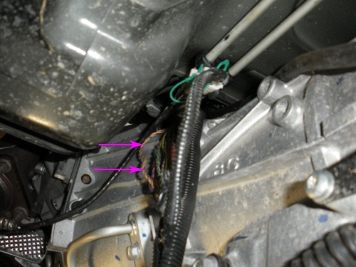
Chafed Wiring Harness at Transmission
- Turn OFF the ignition and all accessories.
- Disconnect the negative battery cable. Refer to Battery Negative Cable Disconnection and Connection in SI.
- Raise the vehicle. Refer to Lifting and Jacking the Vehicle in SI.
- Support the transmission with a transmission jack.
- Remove the transmission support crossmember. Refer to Transmission Support Crossmember Replacement in SI.

- Lower the transmission sufficiently to provide access to the engine wiring harness where it routes from the engine intake manifold to the transmission bell housing as shown.
- Release the wiring harness conduit from the retainers that secure it to the transmission and/or transfer case.
 conduit" width="500" height="375" title="Intermittent No Crank, IP Gage Fluctuation, Intermittent Door Lock Cycling, Intermittent Chime Operation, Various IP Warning Lamps Illuminated, Transmission May Not Shift, Engine May Stall, Communication DTCs - 2007-2014 Cadillac Chevrolet GMC HUMMER 26">
- Examine the harness for wiring that may be exposed outside of the conduit. Inspect all areas for chafed, damaged, pinched, open or shorted wiring as shown. If damage to the wiring is not observed, then extract the wiring from the conduit and inspect all remaining areas as needed.
- If the wiring is damaged, repair as needed. Refer to Power and Signal Distribution > Wiring Systems and Power Management > Diagnostic Information and Procedures > Wiring Repairs. Protect the conduit by covering any sharp edge with butyl tape and the harness with woven polyester (PET) electrical tape. Secure the harness as needed.
- Raise the transmission as needed to install the transmission support crossmember. Refer to Transmission Support Crossmember Replacement in SI.
- Lower the vehicle.
- Connect the negative battery cable. Refer to Battery Negative Cable Disconnection and Connection in SI.
- Clear any DTCs that may be present with a scan tool and verify the proper operation of the vehicle.
Chafed ECM Wiring Harness From Bracket Contact Near Engine Intake Manifold
- Turn OFF the ignition and all accessories.
- Remove the upper intake manifold sight shield. Refer to Upper Intake Manifold Sight Shield Replacement in SI.

- Locate the portion of the engine wiring harness where it branches off from the intake manifold to the ECM in the area shown (1).

- Inspect the wiring harness for damage from contact with the steel bracket (1).
- If the wiring is damaged, repair as needed. Refer to Power and Signal Distribution > Wiring Systems and Power Management > Diagnostic Information and Procedures > Wiring Repairs.
- Cover any sharp edge on the bracket with butyl tape and the harness with woven polyester (PET) electrical tape.

- Protect the wiring harness by adding additional conduit (2) as shown. Tape the conduit to the harness at both ends (1,3) to prevent movement.
- Secure the harness to the bracket with a retaining clip (4) as needed.
Chafed Wiring Harness at Rear of Engine Intake Manifold
- Turn OFF the ignition and all accessories.
- Remove the upper intake manifold sight shield. Refer to Upper Intake Manifold Sight Shield Replacement in SI.

- Remove the retaining plate (2) that covers the wiring harness (1) on the top of the engine intake manifold run channel.

- Gently release and slightly raise the wiring harness (2) from the run channel (1) to allow some slack in the harness.

- Release the wiring harness conduit from the retainers that secure it to the rear of the engine and at the top of the transmission bell housing.

Note: The engine intake manifold is shown removed to provide clarity.
- Gently pull the wiring harness (2) up from the rear of the engine (1).

Inspect for chafed (1), damaged, pinched, open or shorted wiring. If damage is not observed, then extract the wiring from the conduit and inspect all of the remaining areas as needed.
- If the wiring is damaged, repair as needed. Refer to Power and Signal Distribution > Wiring Systems and Power Management > Diagnostic Information and Procedures.
- Protect the conduit by covering any sharp edges on the engine or transmission with butyl tape and the harness with woven polyester (PET) electrical tape.
- Secure the wiring harness within the conduit as needed.
- Attach the wiring harness conduit to the retainers that secure it to the rear of the engine and at the top of the transmission bell housing.
- Secure the wiring harness (2) within the engine intake manifold run channel (1).

- If the vehicle has a small engine wiring harness bundle, secure a portion of the harness within some conduit (1) in the area that will be covered by the retaining plate to prevent movement.
-
Tape both ends of the conduit (1) to the wiring harness.
- Install and secure the retaining plate (2) over the top of the wiring harness bundle (1).
- Install the upper intake manifold sight shield.
- Clear any DTCs that may be present with a scan tool and verify the proper operation of the vehicle.
Chafed Wiring Harness at Chassis Body Mounts Left Side Frame Rail
- Turn OFF the ignition and all accessories.
- Raise and support the vehicle. Refer to Lifting and Jacking the Vehicle in SI.

- Inspect the wiring harness along the left side frame rail at the body mounts as shown for chafed, damaged, pinched, open or shorted wiring.
- If the wiring is damaged, repair as needed. Refer to Power and Signal Distribution > Wiring Systems and Power Management > Diagnostic Information and Procedures. Protect the conduit by covering any sharp edge with butyl tape and the harness with woven polyester (PET) electrical tape. Secure the harness as needed.
- Lower the vehicle.
- Clear any DTCs that may be present with a scan tool and verify the proper operation of the vehicle.
GMLAN Terminator Resistor 2007 Vehicles
- Turn OFF the ignition and all accessories.
- Raise and support the vehicle. Refer to Lifting and Jacking the Vehicle in SI.
Typical Location of Terminator Resistor (1) Short Wheel Base Vehicle

Typical Location of Terminator Resistor (1) Long Wheel Base Vehicle – RPO NQZ

Typical Location of Terminator Resistor (1) Long Wheel Base Vehicle – Except RPO NQZ

Note: RPO NQZ Without Auxiliary Fuel Tank.
- On the vehicle being serviced, observe the location of the terminator resistor. Inspect the wiring harness leading to the terminator resistor, for chafed, damaged, pinched, open or shorted wiring.
- If the wiring is damaged, repair as needed. Refer to Power and Signal Distribution > Wiring Systems and Power Management > Diagnostic Information and Procedures. Protect the conduit by covering any sharp edge with butyl tape and the harness with woven polyester (PET) electrical tape. Secure the harness as needed.
- If the wiring is not damaged, proceed to Step 4.
- Disconnect the electrical connector from the terminator resistor.
- Test the terminator resistor for 110–130Ω.
- If the resistance is not within the specified range, replace the terminator resistor and proceed to Step 6.
- If the resistance is within the specified range, connect the electrical connector to the terminator resistor. Refer to Power and Signal Distribution > Data Communications > Scan Tool Does Not Communicate with High Speed GMLAN Device OR Diagnostic Trouble Code (DTC) List – Vehicle.
- Connect the electrical connector to the terminator resistor. Secure the terminator resistor as needed.
- Lower the vehicle.
- Clear any DTCs that may be present with a scan tool and verify the proper operation of the vehicle.
Data Link Resistor 1 2009 Vehicles
- Turn OFF the ignition and all accessories.
- Raise and support the vehicle. Refer to Lifting and Jacking the Vehicle in SI.
Typical Location of Data Link Resistor 1 (1) Short and Long Wheel Base Vehicles

Typical Location of Data Link Resistor 1 (1) Long Wheel Base HD Vehicles

- On the vehicle being serviced, observe the location of the data link resistor 1 (1). Inspect the wiring harness leading to the data link resistor 1, for chafed, damaged, pinched, open or shorted wiring.
- If the wiring is damaged, repair as needed. Refer to Power and Signal Distribution > Wiring Systems and Power Management > Diagnostic Information and Procedures. Protect the conduit by covering any sharp edge with butyl tape and the harness with woven polyester (PET) electrical tape. Secure the harness as needed.
- If damage is not found, proceed to Step 4.
- Disconnect the electrical connector from the data link resistor 1.
- Test the Data Link Resistor 1 for 110–130Ω.
- If the resistance is not within the specified range, replace the data link resistor 1 and proceed to Step 6.
- If the resistance is within the specified range, connect the electrical connector to the data link resistor 1. Refer to Power and Signal Distribution > Data Communications > Scan Tool Does Not Communicate with High Speed GMLAN Device OR Diagnostic Trouble Code (DTC) List – Vehicle.
- Connect the electrical connector to the data link resistor 1. Secure the data link resistor 1 as needed.
- Lower the vehicle.
- Clear any DTCs that may be present with a scan tool and verify the proper operation of the vehicle.
Rear Chassis Mounted Data Link Resistor 1 Chafed Wiring Harness Causing Intermittent No/Crank and/or Scan Tool Does Not Communicate with High Speed GMLAN Device
- Turn OFF the ignition and all accessories.
- Raise and support the vehicle. Refer to Lifting and Jacking the Vehicle in SI.

- Typical location of a data link resistor 1 (1) mounted on the rear of the chassis.

- Inspect the wiring harness leading to the rear data link resistor 1, between the truck box and frame for chafed, damaged, pinched, open or shorted wiring as shown.
- If the wiring is damaged, repair as needed. Refer to Power and Signal Distribution > Wiring Systems and Power Management > Diagnostic Information and Procedures. Protect the conduit by covering any sharp edge with butyl tape and the harness with woven polyester (PET) electrical tape. Secure the harness as needed. Proceed to Step 9.
- If the wiring is not damaged, proceed to Step 5.
- Disconnect the electrical connector from the data link resistor 1.
- Test the data link resistor 1 for 110–130Ω.
- If the resistance is not within the specified range, replace the data link resistor 1 and proceed to Step 7.
- If the resistance is within the specified range, connect the electrical connector to the data link resistor 1. Refer to Power and Signal Distribution > Data Communications > Scan Tool Does Not Communicate with High Speed GMLAN Device OR Diagnostic Trouble Code (DTC) List – Vehicle.
- Connect the electrical connector to the data link resistor 1. Secure the resistor as needed.
- Protect the conduit by covering any sharp edge with butyl tape and the harness with woven polyester (PET) electrical tape. Secure the harness as needed.
- Lower the vehicle.
- Clear any DTCs that may be present with a scan tool and verify the proper operation of the vehicle.
Inspection of Engine Harness Connector X109 for Backed Out or Bent Terminals and Poor Connections
- Turn OFF the ignition and all accessories.
- Locate the X109 connector. Refer to Wiring Systems and Power Management > Component Locator > Master Electrical Component List > X109.

- Before disconnecting, verify the connector is fully seated together even though the lever is locked down as shown.If the connector is not fully seated, repair as needed. Refer to Power and Signal Distribution > Wiring Systems and Power Management > Diagnostic Information and Procedures > Connector Repairs.
- Inspect the connector for the following conditions:
- Backed out terminals
- Bent pins
- Corrosion
- Poor terminal tension (use the correct test probe)
If a condition is found, repair as needed. Refer to Power and Signal Distribution > Wiring Systems and Power Management > Diagnostic Information and Procedures.
AND
If corrosion is found, proceed to the section of the bulletin titled: Repairing Fretting Corrosion to complete the repair.
- Clear any DTCs that may be present with a scan tool and verify the proper operation of the vehicle.
Inspection of Engine Harness Connector X115 for Backed Out or Bent Terminals and Poor Connections
- Turn OFF the ignition and all accessories.
- Locate the X115 connector. Refer to Wiring Systems and Power Management > Component Locator > Master Electrical Component List > X115.
- Inspect the connector for the following conditions:
- Backed out terminals
- Bent pins
- Corrosion
- Poor terminal fit (use the correct test probe)
If a condition is found, repair as needed. Refer to Wiring Systems and Power Management > Diagnostic Information and Procedures.
AND
If corrosion is found, proceed to the section of the bulletin titled: Repairing Fretting Corrosion to complete the repair.
- Clear any DTCs that may be present with a scan tool and verify the proper operation of the vehicle.
Hybrid (HP2) Chafed Wiring Harness Locations and Inspection of Engine Harness Connector X150 for Backed Out Terminals and/or Poor Connections at Ground Locations G102 and G300
- Turn OFF the ignition and all accessories.
- Locate the X150 connector. Refer to Wiring Systems and Power Management > Component Locator > Master Electrical Component List > X150.
- Inspect the connector for the following conditions:
- Backed out terminals
- Bent pins
- Corrosion
- Poor terminal fit (use the correct test probe)
If a condition is found, repair as needed. Refer to Power and Signal Distribution > Wiring Systems and Power Management > Diagnostic Information and Procedures.
AND
If corrosion is found, proceed to the section of this bulletin titled: Repairing Fretting Corrosion to complete the repair.
If a condition or corrosion is not found, proceed to Step 4.

- Inspect for a misrouted harness having chafed, damaged, pinched, open or shorted wiring from rubbing on the cooling fins of the Transmission Auxiliary Fluid Pump Control Module as shown.
- If the wiring is damaged, repair as needed. Refer to Power and Signal Distribution > Wiring Systems and Power Management > Diagnostic Information and Procedures. Protect the conduit by covering any sharp edge with butyl tape and the harness with woven polyester (PET) electrical tape. Secure the harness as needed. Proceed to Step 8.
- If the wiring is not damaged, proceed to Step 5.

- Inspect for chafed, damaged, pinched or shorted wiring caused by a mispositioned harness retaining clip as shown. This condition usually occurs when the tab of the clip is aligned with a slot in the conduit.
- If the wiring is damaged, repair as needed. Refer to Power and Signal Distribution > Wiring Systems and Power Management > Diagnostic Information and Procedures. Protect the conduit by covering any sharp edge with butyl tape and the harness with woven polyester (PET) electrical tape. Secure the harness as needed. Proceed to Step 8.
- If the wiring is not damaged, proceed to Step 6.
- Locate ground connections G102 and G300. Refer to Wiring Systems and Power Management > Component Locator > Master Electrical Component List > G102 and G300.
- Inspect G102 and G300 for a clean and tight connection. Undercoating or corrosion may be present between the eyelet and the frame resulting in a poor connection.
- If a poor connection or undercoating is found, clean the area and repair as needed. Refer to Power and Signal Distribution > Wiring Systems and Power Management > Diagnostic Information and Procedures.Proceed to Step 8.
- If corrosion is found, clean the area and repair as needed. Refer to Power and Signal Distribution > Wiring Systems and Power Management > Diagnostic Information and Procedures. Proceed to the section of this bulletin titled: Repairing Fretting Corrosion to complete the repair.
- Clear any DTCs that may be present with a scan tool and verify the proper operation of the vehicle.
Hybrid (RPO HP2) Data Link Resistor 2
- Turn OFF the ignition and all accessories.

- Inspect the harness leading to the data link resistor 2 (1) for chafed, damaged, pinched, open or shorted wiring. Refer to Power and Signal Distribution > Data Communications > Schematic and Routing Diagrams > Data Communication Schematics.
- If the wiring is damaged, repair as needed. Refer to Power and Signal Distribution > Wiring Systems and Power Management > Diagnostic Information and Procedures. Protect the conduit by covering any sharp edge with butyl tape and the harness with woven polyester (PET) electrical tape. Secure the harness as needed.
- If the wiring is not damaged, proceed to Step 3.
- Disconnect the electrical connector from the data link resistor 2.
- Test the data link resistor 2 for 110–130Ω.
- If the resistance is not within the specified range, replace the data link resistor 2 and proceed to Step 5.
- If the resistance is within the specified range, connect the electrical connector to the terminator resistor. Refer to Power and Signal Distribution > Data Communications > Scan Tool Does Not Communicate with High Speed GMLAN Device OR Diagnostic Trouble Code (DTC) List – Vehicle.
- Connect the electrical connector to the data link resistor 2. Secure the resistor as needed.
- Clear any DTCs that may be present with a scan tool and verify the proper operation of the vehicle.
Hybrid (HP2) Equipped With OnStar Delete RPO UE0 — IP Junction Block Jumper Harness Loop Connector Chafed Wiring
Various Symptoms and/or Powertrain and Communication DTCs Set
The following is a list of some of the DTCs that may be set and is not all inclusive: C0242, P0700, P0AC4, U0293, U0100, U0109, U0129, U0140, U1862, U186B, U1886 or U1888.
- Turn OFF the ignition and all accessories.
- Disconnect the negative battery cable. Refer to Battery Negative Cable Disconnection and Connection. Refer to Battery Negative Cable Disconnection and Connection in SI.

- Locate the junction block (1) on the driver side of the vehicle under the instrument panel (IP).

- Locate the jumper harness loop connector that plugs into the bottom back of the junction block.

- Inspect the jumper harness loop connector (1) for chafed (2), damaged, pinched, open or shorted wiring from contact with the IP brace.
- If the wiring is damaged, repair as needed. Refer to Power and Signal Distribution > Wiring Systems and Power Management > Diagnostic Information and Procedures. Protect the harness by covering any sharp edge with butyl tape and the harness with woven polyester (PET) electrical tape. Secure the jumper harness loop connector as needed. Proceed to Step 6.
- If the wiring is not repairable, replace the P/N 15127940 jumper harness loop connector. Protect the connector by covering any sharp edge with butyl tape and the jumper harness loop connector wiring with woven polyester (PET) electrical tape. Secure the harness as needed. Proceed to Step 6.
- Secure the junction block as needed.
- Connect the negative battery cable. Refer to Battery Negative Cable Disconnection and Connection.
- Clear any DTCs that may be present with a scan tool and verify the proper operation of the vehicle.
Lost Communication with Various Control Modules and DTCs Set
DTC Descriptors
Note: Depending on the vehicle and vehicle build there may be other DTCs set by other modules.
- DTC U0073 Control Module Communication Bus A Off
- DTC U0100 Lost Communication with Engine/Powertrain Control Module (ECM/PCM)
- DTC U0101 Lost Communication with Transmission Control Module (TCM)
- DTC U0102 Lost Communication with Transfer Case Control Module
- DTC U0121 Lost Communication with Electronic Brake Control Module (EBCM)
- DTC U0140 Lost Communication with Body Control Module (BCM)
- Connect a scan tool and perform the Diagnostic System Check – Vehicle. Retrieve and record any DTCs, Current or in History from all of the control modules.
If any DTC(s) are set, refer to Diagnostic Trouble Code (DTC) List – Vehicle to identify the connector(s) of the control module/component which may be causing the condition.
- Turn OFF the ignition and all accessories.
- Disconnect the connector(s) at the affected module.
- Inspect the connector(s) for the following conditions:
- Backed out terminals
- Bent pins
- Corrosion
- Poor terminal tension. Use the correct test probe.
- Water intrusion
- If a condition is found, repair as needed. Refer to Power and Signal Distribution > Wiring Systems and Power Management > Diagnostic Information and Procedures.
Proceed to Step 5.
- If corrosion or water intrusion is found, proceed to the section of this bulletin titled: Repairing Fretting Corrosion to complete the repair.
- Reconnect the connector at the affected module.
- Clear any DTCs that may be present with a scan tool and verify the proper operation of the vehicle.
Inspection of Electronic Suspension Control (ESC) Module Connector for Missing Weather Plugs in Not Used Cavities (RPO Z55 or G69)
- Turn OFF the ignition and all accessories.
Typical Location of ESC Module

- Locate the ESC module (1).
- Disconnect the connector (2) at the ESC module (1).
Typical View of Missing Weather Plug

- Inspect the connector of the ESC module for weather plugs that are missing from: Not Used cavities (1). Refer to > Power and Signal Distribution > Wiring Systems and Power Management > Component Locator > Master Electrical Component List > Electronic Suspension Control (ESC) Module > Connector End View for a list of cavities that are: Not Used.
- If a weather plug is missing from any Not Used cavity, repair as needed.
- Install the connector (2) to the ESC module (1).
- Clear any DTCs that may be present with a scan tool and verify the proper operation of the vehicle.
Repairing Fretting Corrosion
Note: Fretting corrosion looks like little dark smudges on the electrical terminals and appear where the actual electrical contact is being made. In less severe cases it may be unable to be seen or identified without the use of a magnifying glass.
- If water intrusion is observed in the connector, use pressure regulated compressed air to dry it out.

- DO NOT apply an excessive amount of dielectric lubricant as shown, to the connectors as hydrolock may result when attempting to mate the connectors. This could cause terminals to back out, resulting in an intermittent connection.
Important: Use ONLY a clean nylon brush that is DEDICATED to the repair of this specific condition.
Using a one-inch or smaller nylon bristle brush, apply dielectric lubricant P/N 12377900 (in Canada P/N 10953529) to both the module or component side and the harness side of the affected connectors.
- Reconnect the affected connector(s) and wipe away any excess lubricant that may be present.
- If needed, connect the negative battery cable. Refer to Battery Negative Cable Disconnection and Connection.
- Clear any DTCs that may be present with a scan tool and verify the proper operation of the vehicle.
OnStar is a registered trademark of the OnStar Corporation.
Parts Information
| Part Number | Description | Material Allowance |
| 22124472200 | J-38125 Terminal Repair Kit, Yazaki Tray Number 12 – Female Terminal | — |
| 88988999 |
RESISTOR – DATA LINK | — |
| 12377900 |
Dielectric Lubricant (50 gram tube) | $11.56 (USD) ($2.90 per repair) |
| 10953529 | (in Canada) Dielectric Lubricant (50 gram tube) | $17.35 (CDN) ($4.35 per repair) |
| – | Woven Polyester (PET) Electrical Tape | $22.72 ($3.00 per repair) |
Warranty Information
For transmission electrical repairs please note in the technicians comments field on the repair order which terminal number(s) were repaired or replaced. Also if a male terminal is bent (transmission side of connector), then indicate the bent terminal number on the repair order.
For vehicles repaired under warranty, use:
| Labor Operation | Description | Labor Time |
| 5430840 | Terminal Replacement | Use Published Labor Operation Time |
| 5430902 | Wire to Wire Repair | |
| 5430922 | Connector Reconnection | |
| 5430962 | Ground Stud or Nut Repair or Replacement | |
| 5430190 | Block Assembly, Wiring Harness Junction – Left Body and Instrument Panel Replace | |
| 2680278* | Lubricate Body Control Module (BCM) Connector With Dielectric Lubricant | 0.1-0.3 hr |
| 2680288* | Lubricate Engine Control Module (ECM) Connector With Dielectric Lubricant | |
| 2680298* | Lubricate Transmission Control Module (TCM) Connector With Dielectric Lubricant | |
| 2680308* | Lubricate Electronic Brake Control Module (EBCM) Connector With Dielectric Lubricant | |
| 2680318* | Lubricate“Other” Connector With Dielectric Lubricant** | |
| 2680328* | Repair and Reroute IP Wire Harness Near Park Brake | 0.8 hr |
| *This is a unique Labor Operation for Bulletin use only. It will not be published in the Labor Time Guide.
**You Must Document the Affected Connector on the Repair Order. Note: Any additional time for component R&R to gain access or for repair time greater than 0.3 hr must be submitted as Other Labor Hours and requires appropriate authorization and service management approval. |
||
SEOCONTENT-END
Bulletin No.: 08-07-30-021H
Date: Jun-2015
To View or Download this Document Click Here
 Loading...
Bulletin No.: 08-07-30-021G
Date: March, 2012
To View or Download this Document Click Here
Loading...

- [Pro OBD2 Scanner] - BlueDriver is the easiest way to scan and understand your vehicle like a professional mechanic. Read and clear your car’s trouble codes and check engine light.
- [Read & Clear All The Codes] - BlueDriver's enhanced vehicle diagnostics gives you access to information normally available only to mechanics on their OBD2 scan tools. Now you can read and clear ABS, Airbag, SRS, TPMS codes, and many more.
- [Get The Right Fix & View Live Data] - Much more than a car code reader, BlueDriver is a diagnostic tool. You’ll get unlimited repair reports with possible causes and fixes, plus real-time health monitoring while you drive with the live data feature.
- [Wireless & Bluetooth Enabled] - Say goodbye to wires. BlueDriver connects with Bluetooth via your phone/tablet to a sensor that plugs into your car's OBDII port. Get all of the capabilities of an expensive code reader & scan tool without any annoying wires.
- [User-Friendly App and Repair Videos] - BlueDriver gives you more ways to scan and fix your vehicle. Our iOS & Android app connects you to a large database of repair videos with step-by-step directions of repairs.

- 🔥🔥🔥【2025 NEWLY RELEASED BI-DIRECTIONAL CONTROL】As the 2025 upgraded version of MaxiChek MX808, our Newest MK808S auto diagnostic scanner for all cars inherits the powerful Bi-directional Control which makes it the most cost-effective Autel scanner (without breaking the bank, same as MP900BT and MS906 PRO). Active test is widely used on car subsystems to help you check if the car actuators are all in good condition. Such as windows, rear mirrors, sunroof, wipers...
- 【28+ MOST POPULAR RESET SERVICE FOR 150 MAKES】Autel versatile OBDII scanenr MK808S, full level-up of MX808, work as MX900, MK900, MK900BT, supports 150+ car brands worldwide & FCA AutoAuth. Like the OBD2 code reader MaxiCOM MK808BT Pro, MK808S is equipped with 28+ hot services including Oil Reset, SAS Calibration, ABS Bleeding, Injector Coding, Battery Registration, etc. MK808S ranks top in professional automotive tablets and keeps updating to support more newer modes from 2023 to 2025.
- 【ALL SYSTEM DIAGNOSTICS, FACTORY-LEVEL SCANNER】The MK808S dealer-level scanner, like Snap-on tools, effectively works all cars for all system diagnostics. It reads/clears codes, provides ECU info, displays 5-in-1 Live Data, performs active tests, and special functions for all available modules. With a few clicks, you can easily understand the vehicle's condition. The convenient Wi-Fi printing feature allows you to generate a detailed report, highlighting the exact nature of the problem.
- 【AUTO SCAN & AUTOVIN, 5X FASTER】How much have you spent on car maintenance? Even a minor issue can take up a significant amount of time. The MK808S is designed to improve your work efficiency. With its AutoVIN technology, you can identify your vehicle's make, model, and year information with just one click. The convenient AutoScan feature automatically scans all of the vehicle's ECUs and detects any fault codes. Check AutoVIN compatibility, please contact us at 📞 MotorzoneUS @ outlook . com 📞
- 【WHY MK808S STANDS OUT】✅Autel's escaner automotriz professional, MK808S, provides the same funcntions as the MK808BT PRO at a lower cost. MK808S not only helps you save on subscription expenses (124.5 USD vs. 150 USD) but also ensures flawless utilization of all functions even without updates. ✅As Autel's flagship model, MK808S is the upgraded version of the old MX808 MK808BT. It covers global coverage for 150 car brands, making it a versatile and cost-effective choice.

- 2025 Advanced online ECU coding: Maximize the capabilities of your vehicles with the ArtiDiag Pro ECU Coding tool. This scan tool, seamlessly compatible with renowned models such as VW, A-U-D-I, SKODA, SEAT, BENZ, and more, empowers you to uncover hidden features, deactivate annoying functions, and code retrofitted components for peak performance. Ensure a backup before coding and steer clear of coding sessions on low battery levels.
- Efficient Diagnostics with Bidirectional Control: Say goodbye to uncertainty, streamline diagnostics, and reclaim valuable time with ArtiDiag Pro scan tool. This bidirectional scan tool exceeds expectations, enabling targeted tests on individual actuators to swiftly identify and resolve issues. Covering lights, door locks, fuel and coolant systems, windows, wipers, EVAP, and more in vehicle components.
- 35+ Services Resolve 90% of Repair Challenges: Unleash maximum productivity with the ArtiDiag Pro, a scan tool that tackles 90% of maintenance issues through its 31 special functions. Effortlessly clear oil maintenance indicators with oil reset. Engage the EPB Reset for brake system management and establish precise alignment with the Steering Angle Reset to define the straight-line reference position for your vehicle.
- FCA Autoauth : This diagnostic tool supports Autoauth for FCA SGW, Chrysler, Jeep, Dodge, Fiat etc. 2017 and later. NOTE: Due to Product Upgrade, there is no Chrysler 12+8 adapter, the BMW-20 Adapter in the package any more. We are sincerely sorry for the inconvenience. NOTE: Please confirm compatibility before purchase.(Topdon Website>Support>Vehicle Coverage)
- Professional Customer Support: At TOPDON, your satisfaction is our unwavering commitment. Experience hassle-free support and a lifetime of expert assistance. Should you encounter any challenges, reach out to us at 833-629-4832. For returns, please damage the packaging to prevent Amazon from reselling it. Please be advised that after two years, a fee of 249 Bucks will apply for software updates.

- OE-Level diagnostics on your smart device
- FREE Software updates - No subscriptions, no fees – EVER
- Full bi-directional control, live actuation test
- Supports 23 vehicle reset/relearn functions, including throttle matching, ABS bleeding, TPMS reset, etc.
- Live data mapping and freeze frame capturing

- [13+ Hot Service Functions for Complete Vehicle Care] - Unlock the full potential of your vehicle with the Topscan Pro, the upgraded version of the Topscan Lite. This powerful OBD2 bluetooth scanner supports 13 service resets, a significant upgrade from the Lite's 8 reset service functions. With a wide array of capabilities like oil reset, throttle adaptation, EPB reset, DPF regeneration, ABS bleeding, airbag reset, injector coding, and more, it ensures your vehicle stays in peak condition, making it the ultimate diagnostic scan tool for all vehicles.
- [Comprehensive Full Systems Diagnostic] - This obd2 scanner diagnostic tool provides wireless all system diagnostics, making it an indispensable automotive tools. It supports OBDII/EOBD protocols, enabling thorough diagnostics across all major vehicle systems, including the engine, ABS, SRS, transmission, and more.
- [Bi-directional Control] - Transform your driving experience with our advanced bidirectional scan tool. Designed for convenience and enhanced functionality, this system allows you to effortlessly manage your vehicle's features from both inside and outside.
- [FCA Gateway Access & Flexible Subscription Plans] - The TOPDON TopScan offers enhanced support with FCA Gateway Access, allowing you to perform protected functions on FCA vehicles, including Chrysler, Dodge, Jeep, Fiat, and more. Enjoy no subscription fees for the first year with the TopScan, giving you access to advanced features at no additional cost. After the first year, choose the subscription plan that best suits your needs with monthly, quarterly, and yearly options available for maximum flexibility.
- [Live Data Functionality] - Unlock real-time insights into your vehicle's performance with our escaner automotriz's Live Data function. This advanced feature allows you to monitor engine parameters and system performance on the go, providing valuable information for troubleshooting and maintenance.

- 🚦📢【NOTE: Please Check Compatibility Before Order】➊ ABS bleed works with limited Specific Vehicle models, most vehicle Year under 2015 or older vehicles, For GM, up to 2018. ➋ All the functions are Not universal for each vehicle. Please contact us to check the compatibility before ordering via 📩Autelchoice @ outlook . com📩, offer us your detail Car Model, Year, VIN# (IMPORTANT), and the functions you need, and you will get the available solution in 12 hours.
- 💪【ABS Auto Bleed & ABS Bi-Directional Control】Autel scanner MaxiCheck Pro allows you to check the operating conditions of the ABS Braking System, such as Automated Bleeding. ABS Brake Bleeding enables technicians and home mechanics to bleed air out of the ABS module and saves you time and money. Use this to first bleed the ABS module which will force any air into the brake lines. Then you can do a brake bleeding as usual. Note: Your vehicles must be programmed by the manufacturer to perform auto-bleed.
- 💪【 Hot Service Functions for Limited Vehicles】Service & Special functions such as ABS Automated Bleed, Oil Reset, ABS, SRS, EPB, SAS, BMS, Airbag are limit. Please contact us via 📩Autelchoice @ outlook . com📩 to check the compatibility before ordering by offering your detail Car Model, Year, VIN# (IMPORTANT), and the functions you need, you will get the available solution in 12 hours.
- 💪【ABS, SRS Diagnosis & OBD2 Function cover 10 Modes】 MaxiCheck Pro auto bleed scanner performs ABS, SRS Scan to read and clear ABS, SRS, OBDII fault codes, covers all 10 modes of OBD2 tests including read & clear codes, view freeze frame data, I/M Readiness Status(Smog Check), Component Test, O2 Monitor Test, On-Board Monitor Test, Live Data, DTC Lookup, Vehicle Info, Module Present on ALL OBD2 compliant vehicles.
- 💪【Lifetime Free Updates, 1-Year Warranty, 24/7 Tech Support】Customer service team is available for 24 hours and we will offer solutions or a full refund, if you need any Tech Support or After Service. NOTE: Japanese vehicles like Toyota/Honda, please check with a dealership whether your car comes with the Auto Bleeding before purchase.

- 【Recom-mended by YouTube Machinists】We are proud to tell that LAUNCH X431 PROS V+ 5.0 has been recom-mended as "" Per-fect Overall Car Diagnostic Scanner "" by famous editors, and also highly recom-mended by YouTube machinists.
- 【What Are the 2025 PROS V+ 5.0 Hardware Changes】With new in-house developed screen; 8.0 MP Pixel Rear Camera;Android 10.0 System; 2.4GHz&5GHz Dual-Frequency Wi-Fi, the transmission rate is 4Xfaster than old version; 4+64GB provides larger data memory; 6300mAh battery lasts 15+h work; CPU Updated to 2.0 GHz quard-core. greatly increased the speed of running multiple task; 8XFAST AUTO VIN technology;DBSCar VII connector equipped with indicator lights, which is more intuitive and user-friendly
- 【Technology Itself is Proof of Quality】LAUNCH DBSCar VII+Self-developed screen.Using USB type A/USB type C connectors and DBSCar VII VCI connector can make the process of diagnosing and matching faster and more stable, DBSCar VII connector equipped with indicator lights, which is more intuitive and user-friendly. The latest self-developed screen from LAUNCH, in addition to its strong anti-fall ability, is different from other launch models in sensitivity and touch.
- 【2025 Newly Added CANFD】With the CANFD Connector, you can seamlessly diagnose a wider range of vehicle models (up to model year 2025, see image below for supported models) using advanced CANFD protocols. Gone are the days of being limited to certain models - now you can confidently handle the latest models, even those with the most advanced systems.
- 【Bi-Directional+Online Coding+Over 38 Reset Services+Adaptation+Initialization+ Matching】PROS V+ 5.0 scan tool Elite also support:K-EY programming,Gear/ SAS/ EPB/ TPMS/ BMS/ETS/Oil/Brake/AFS/GEARBOX/SUNROOF/SUS Reset,ABS Bleed, Injector coding.Gives you the ability to use dealership level relearn procedures to complete repairs.You can get 100+ advanced special functions under the""vehicle brand""-""menu""-""system"" - ""special functions"".

- 📢👉【NOTE: Please Check Compatibility Before Order】ABS bleed works with limited Specific Vehicle models, most vehicle Year before 2015 or older vehicles; For GM, up to 2018. Besides, all the functions are Not universal for each vehicle. Please reach us via [ autelonline @ outlook . com ] and offer your detail Car Model, Year, VIN# (IMPORTANT), and the functions you need, and you will get the available solution in 12 hours.
- 👨🔧【 How to Make Sure Your Car has Auto Bleed Function 】NOT ALL vehicle makes and models are capable of perform the auto bleed. It is NOT the scan tool RUNNING the auto bleed, it is the vehicle's ECM (co.mputer) in the vehicle itself that runs the auto bleed, the scan tool is just simply commanding that function. 📢👉Note: for many Asian Japanese cars, for example, toyota cars, it's uncertain. Workshops/ DIYers need to confirm with dealers if a car itself has autobleed ability before order an autobleed tool. So please make sure your vehicle is programmed from the factory to perform auto bleed or contact us for confirm before order!
- 👨🔧【 Multi-Service Functions Included 】Perform Service Maintenance and Oil, Inspection and Mileage Resets. Oil Light Reset. Battery Maintenance Services. View Freeze Frame Data to view the vehicle's operating parameters at the moment code is detected. ABS and SRS Coverage for 50+ Vehicle Makes. Perform various diagnoses & special functions like ABS, SRS, Oil Reset, EPB, BMS, etc. 📢👉Note: Functions are NOT universally compatible. Before ordering, please send us your detail Car Model, Year, VIN# (IMPORTANT), and the functions you need to check the compatibility.
- 👨🔧【 Complete OBDII/EOBD Coverage 】Read Codes, Erase Codes, DTC Lookup for 1996 and newer U.S. Domestic, Asian & European vehicles. Live Data, I/M Readiness Status(Smog Check), O2 Monitor Test, On-Board Monitor Test & Component Test, view freeze frame data, Component Test, DTC Lookup, Vehicle Info, Module Present on ALL OBD2 compliant vehicles.
- 👨🔧【 Lifetime Free Update & Lifetime Tech-support 】Enhanced OBD2 Coverage for Domestic, Asian & European Vehicles, enjoy free software update. 🎯For better useing experience, please update the software to the latest before use to find more vehicle coverage. Maxicheck pro comes with life-long time tech-support. If you have any concerns about Maxicheck Pro, please send VIN to us to check compatibility.

- 🔥🔥🔥【2025 Autel Impressive MK808BT PRO, Powerful And Cost-Effective Than Autel MK808S MK900 MX900 MK900BT MX808S】Upgraded of the wired OBD2 code reader MaxiCOM MK808S MK808, functioning as MK900BT (save 100+USD), Autel scanner MK808BT PRO features bidirectional control as MS906 PRO, making it the most powerful & cost-effective Autel bidirectional scanner. It makes a great leap: 28+➡40+ Resets, 50+➡3000+ Active Tests, 2G➡4G, 16G➡64G, 0.9m➡10m working range, eli.minating cable limit. 7in user-friendly UI for BT506 battery test(NOT by other maxicom 808 900 series cable OBD scanners like: Autel MK808 MK808Z MK900 Autel MX808, etc.).
- 👍【New Next-Level Bidirectional Control, 50➡3000+ Tests, Same As MS906 PRO】Unlike the Autel MS906BT MS906 DS808 MP808 MK808 and MX808 car diagnostic scanners, which offer only 50 functional tests, the Autel bidirectional scan tool MK808BT PRO features over 3000 active tests. These tests are widely used on car subsystems to help technicians quickly check if the car's actuators are functioning properly. Such as ABS, windows, rearview mirrors, wipers, sunroofs, fuel injectors, AC clutches, coolant fans, radiator fans, coolant pumps,etc. Warm Note📢: All functions are vehicle-specific, not universal to all vehicles,pls send VIN to 📞auteldirect @ outlook . com📞check compatibility before order.
- 👍【28+➡40+ Hot Services for 150+ Makes】Autel scan tool MK808BT PRO, upgraded with a BT VCI Mini(valued at 120USD), surpasses the old wired OBDII scanner MK808S MK900, by providing a convenient 10m wireless working range, offering greater freedom and comfort compared to the 0.9m cable limit of the MK900 MK808S car scanner. New features include VIN Check across different modules for comparison and 40+ resets, such as injector coding, ABS autobleed, Oil reset, SAS cali.bration, BMS, throttle relearn, suspension adjustments,etc.
- 👍【All Available Module Diagnosis - OE-Level Scanner】The OE versatile OBDII scan tool MK808BT PRO escaner para autos effectively works with all car systems: ABS, ECM, BCM, SRS, TCM,etc. It identifies vehicles via AutoVIN/manual input/select, like S.nap-on tools, it can ✔read/clear 7000+ DTCs, ✔read ECU info, ✔view 5-in-1 live data, ✔perform active tests, and ✔reset services. ✔Reports can be shared via QR-code and printed, working globally and 21+ multilingual. Supports 150+ US/EU/Asian makes, with ongoing updates from 2023 to 2025. Note📢: The AutoVIN function usually works for post-2006 cars, depending on whether the vehicle's VIN is stored in the ECU. You can always do manual input/select.
- 🏆【Test Battery with BT506 (MK808S MK900 are Not Supported)】Autel MK808BT PRO diagnostic scan tool, when paired with the BT506, performs professional cranking/ charging system tests and in-vehicle and out-of-vehicle battery tests with 98%+ accuracy, thanks to advanced adaptive conductive - significantly higher than the market average of 50%. Tests all 6V/12V batteries with 100-2000 CCA, incl. popular types: Flooded, AGM, AGM Spiral, EFB, GEL batteries. Compatible with CCA, CA, SAE, EN, IEC, DIN, JIS and MCA standards.

- 【WHY CHOOSE THE 2025 CR PRO+? 】THE MOST COST-EFFECTIVE BIDIRECTIONAL OBD2 SCANNER, COSTING 80 LESS THAN CR MAX, WITH THE SAME 49+46 BRAND-SPECIFIC MAINTENANCE SERVICES & ECU CODING ABILITY AS CR MAX, CR Pro+ performs more in-depth services and active test than other brands. Unlike others only do basic oil/SAS reset, and wiper/lamp test, CR Pro+ of 2.0GHz quad-core CPU dives more deeper to test for complex hardware response, actuator condition, ECU functionality, and performs more targeted maintenance services with more professional hardware, sensors and control unit services. NOTE-The ECU Coding functions ONLY work for AU DI/BM W/ V W.
- 【POWERFUL BI-DIRECTIONAL CONTROLS】iCarsoft Pro+ (2025) enables to test more detailed and complex units than other-brand scanners, for example, for Porsche 911 stepless electronic fan module- letting you diagnose cooling system issues before they cause overheating damage, continuous oxygen sensing - LSU, and attaching brake pads, and more. Wiith this tool you can efficiently identify the fault source, avoid unit waste due to "blind unit- guessing" repairs. NOTE:The supported actuation test functions vary by vehicle models, please contact us to check compatibility.
- 【COST-EFFECTIVE 49 RESET SERVICE】 The iCarsoft Pro+ 2025 features full Reset/ Adaptation/ Calibration/ Initialization/ Relearn/ Match service with Full ECU diagnostic, including ABS Reset/ Oil Reset/ EPB Reset/ ETC Reset/ INJ Reset/ SAS Reset/ BLD Reset/ BMS Reset/ LAP Reset/ SPS Reset/ TPMS Reset/ACS Reset/ AFS Reset/ FPP Reset/ IDL Reset/ BSC Reset/ Door Reset/ Seat Reset/ TCM Reset/ Service Interval Reset/ Brake Reset/ DWR Reset/ ECM Reset etc, and other special functions based on car brands. NOTE:The supported reset functions vary by vehicle models, please contact us to check compatibility.
- 【OE Multi-SYSTEMS DIAGNOSTICS】Unlike other scanner's limited systems diagnostic, CR Pro+ digs deeper across much more systems and sub-systems,like Engine, TCM, ABS, Airbag, Brake, BMS, Battery, electronics, windows, etc, helping you detect existing faults and potential faults. CR Pro+ powerfully decode multi systems, giving you complete vehicle health analysis - not just isolated systems. It displays module Info, real-time data graphs, such as transmission temperature, saves freeze frames to pinpoint intermittent faults. Note: Available systems vary by model. TIP:Each car model has unique systems. Please contact us to confirm which systems are available for your vehicle.
- 【Advanced 49 Reset + 38 Brand-Specific Services】 CR Pro+ covers 49+ system resets and has brand - specific reset functions. As mileage grows, more units require maintenance. Our reset tool suit both individual car owners and mechanics. Post - emergency repairs, our tool enables quick resets, restoring vehicle condition and saving dealership reset costs.For repair shops, cut outsourcing, earn more per order, reset in 2 minutes. NOTE:The supported reset functions vary by vehicle models, please contact us to check compatibility.
Last update on 2025-05-09 / Affiliate links / Images from Amazon Product Advertising API
This product presentation was made with AAWP plugin.