| “This site contains affiliate links for which OEMDTC may be compensated” |
NHTSA ID Number: 10126380
Manufacturer Communication Number: PI1539
Summary
This preliminary informational bulletin provides information on the introduction of the new 2.8L Duramax diesel engine for the 2016 midsize pickup trucks, to help the service department personnel become familiar with some of the vehicles new features and to describe some of the action they will need to take to service this vehicle.
2 Affected Products
Vehicles
SEOCONTENT-START
Bulletin No.: PI1539
Date: Oct-2015
| Subject: | 2016 Colorado/Canyon Duramax Diesel New Model Features |
| Models: | 2016 Chevrolet Colorado — Crew Cab Models |
| 2016 GMC Canyon — Crew Cab Models | |
| Equipped with Duramax Diesel 2.8L, DI, L4, DOHC, TURBOCHARGED – RPO LWN | |
| Equipped with Hydra-Matic 6L50 6-Speed Automatic Transmission – RPO MYB | |
| Equipped with 2WD or 4WD | |
| United States and Canada Only |
Overview
Become familiar with the available 2.8L Duramax diesel engine for the 2016 Chevrolet Colorado and 2016 GMC Canyon midsize pickup trucks.
A diesel engine was part of the Colorado/Canyon portfolio plan from the very beginning of the vehicle’s introduction, meaning the chassis, suspension and other elements of its architecture were engineered to support its capability upon implementation.
Colorado
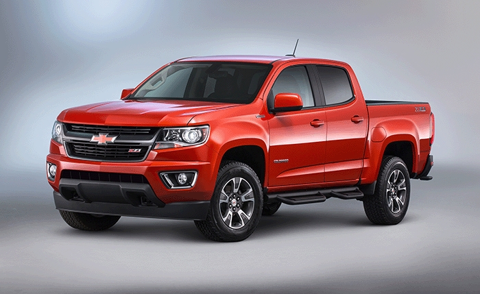
The Duramax diesel engine will be available in the Fall of 2015 and it offers additional truck capability and versatility to customers who don’t require a fullsize truck.
The 2.8L Duramax diesel is the cleanest diesel truck engine ever produced by General Motors . It will be offered in LT and Z71 Crew Cab models with 2WD or 4WD.
Canyon
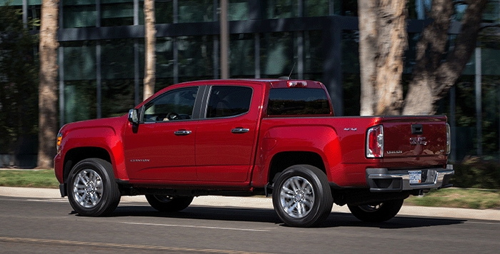
The Duramax diesel engine will be available in the Fall of 2015 and it offers additional truck capability and versatility to customers who don’t require a fullsize truck.
The 2.8L Duramax diesel is the cleanest diesel truck engine ever produced by General Motors . It will be offered in SLE and SLT Crew Cab models with 2WD or 4WD.
Additional Vehicle Features
- When properly equipped, both vehicles offer a maximum trailering capability of 7,700 lbs (3,492 kg) for 2WD models and 7,600 lbs (3,447 kg) for 4WD models.
- The Hydra-Matic 6L50 6-speed transmission is matched with a centrifugal pendulum vibration absorber (CPVA) integrated in the torque converter which reduces powertrain noise and vibration.
- The available trailering package includes a hitch receiver, seven-pin connector, as well as the segment exclusive automatic locking rear differential.
- A 3.42:1 rear axle ratio and four wheel disc brakes with Duralife brake rotors are standard. Duralife™ brake rotors are expected to last twice as long as conventional rotors and provide quieter braking with less vibration.
- An all new integrated trailer brake controller is standard and exclusive to the Duramax diesel models.
- A smart diesel exhaust brake system that enhances vehicle control and reduces brake wear on steep grades.
- Gross vehicle weight ratings (GVWR) of 6,000 lbs (2,721 kg) for 2WD and 6,200 lbs (2,812 kg) for 4WD.
- A new electronically controlled two-speed transfer case is available on 4WD models.
- A fully boxed frame provides the strength to enable the capabilities of the new Duramax diesel while supporting a ride designed to be smooth and quiet. The Colorado and Canyon feature three sections – or bays – with specific strength and support characteristics, including a front bay made of hydroformed side rails and an integrated four-point front axle mounting system designed to reduce vibration.
2.8L Duramax Turbocharged Diesel Engine
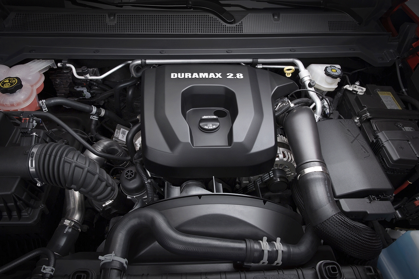
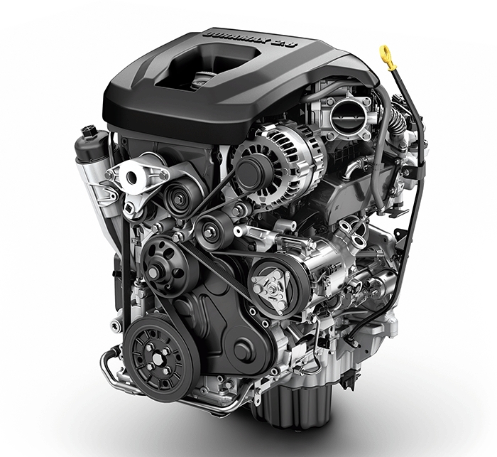
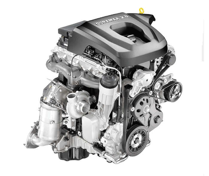
The new to North America, 2.8L Duramax diesel engine is part of GM’s global family of turbo diesel four cylinder engines designed to deliver value, capability and efficiency.
It is a no compromise turbocharged engine with excellent responsiveness.
It was designed specifically for trucks and has undergone many of the same durability and reliability validation tests as the 6.6L Duramax.
Engine Specifications and Features
The following are some of the engine specifications and its features:
- Engine Type: 2.8L Duramax inline 4 cylinder turbocharged diesel.
- Displacement: 2.8 liters, 170 cubic inches.
- Peak Horsepower: SAE certified at 181 horsepower (135 kW) at 3,400 rpm.
- Peak Torque: SAE certified at 369 lb-ft (500 Nm) of torque at 2,000 rpm. A broad torque band makes it very powerful at low rpm while the turbocharged performance provides immediate and smooth horsepower on demand.
- Engine Block Material: Cast iron cylinder block, machined in-house at GM’s plant in Rayong, Thailand.
- Cylinder Head Material: Cast aluminum alloy with newly enlarged exhaust ports, bigger water passages and an improved oil distribution channel for in-head lubrication.
- Compression Ratio: 16.5:1
- Bore: 3.70 inches (94 mm).
- Stroke: 3.94 inches (100 mm)
- Fuel Injection: Direct injection, high pressure, solenoid operated injectors at 29,000 psi (2000 bar) with a common rail. High pressures improve engine efficiency and performance and reduce CO2 and fuel consumption.
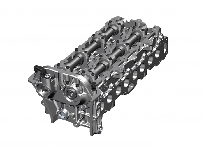
- Valvetrain: Dual overhead camshafts (DOHC), 16 valves (4 valves per cylinder) with a roller finger follower actuator system. Valve springs are standard and the seats are sintered metal pressed in, then later machined.
- Camshafts: The camshafts are tubular, utilizing cast steel sintered lobes that are pressed onto the camshaft and then machined to profile.
- Crankshaft: Forged steel crankshaft, machined in-house at GM’s plant in Thailand. The crankshaft is fully balanced.
- Connecting Rods: Forged steel connecting rods.
- Pistons, Rings and Cooling: Traditional deep-dish design cast aluminum pistons with floating piston pin, cored oil cooling gallery with oil cooling jets and three ring design — a top, middle and oil ring.
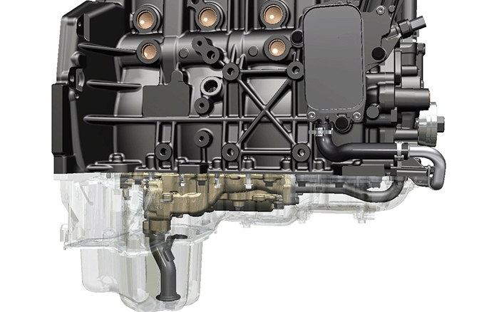
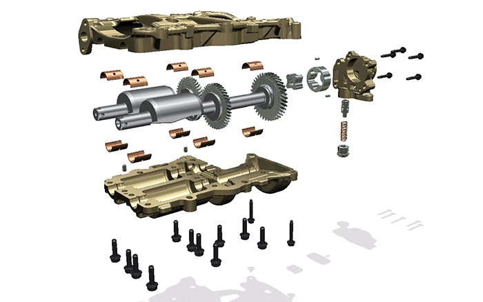
- Balance Shaft: The balance shaft is more centered in the engine, which contributes to increased smoothness. The balance shaft assembly is bolted to the bottom of the cylinder block. It is driven from a gear at the rear of the crankshaft. The balance shaft also drives the oil pump gear-to-gear.
- Oil Pan: The laminated steel oil pan is assembled with an upper aluminum section that contributes to engine rigidity and quietness.
- Ceramic Glow Plugs: Ceramic glow plugs provide shorter heat-up times and higher glow temperatures than metallic glow plugs.
- Cooled EGR: The cooled EGR contributes to lower emissions by diverting some of the engine-out exhaust gas and mixing it back into the fresh intake air stream, which is drawn into the cylinder head for combustion. That process lowers combustion temperatures and rates, improving emissions performance by reducing the formation of NOx.
- Variable Geometry Turbocharger (VGT): A water-cooled VGT provides optimal power across the engine RPM band. It uses an oiling circuit that includes a dedicated feed for the VGT to provide increased pressure at the turbocharger and faster oil delivery. The compressor wheel was retooled to optimize high-altitude capability and to meet emissions standards at the higher altitudes that may be encountered in certain areas of North America.
- Composite Intake Manifold: A composite intake manifold is used on this engine for weight reduction and to reduce the transfer of engine noise.
- Biodiesel Fuel: The engine is B20 biodiesel fuel capable.
- Soft Timing Belt: The engine uses a soft timing belt that’s good for a 150,000 mile service interval. It was selected for packaging, lower noise production and serviceability to −40°F (−40°C).
- Optional Block Heater: The optional block heater is a wet heater through the side of the engine block for those extreme below −20°F (−29°C) temperatures. The heater is attached through a cast-in port and it can be retrofitted through the block plug if a used vehicle is bought but didn’t ship with one originally.
- Integrated Engine Oil Filter and Integrated Engine Oil Cooler: The engine uses an integrated engine oil filter and an integrated engine oil cooler. The oil filter is a cartridge-style paper filter designed for ease of service and accessibility in the vehicle.
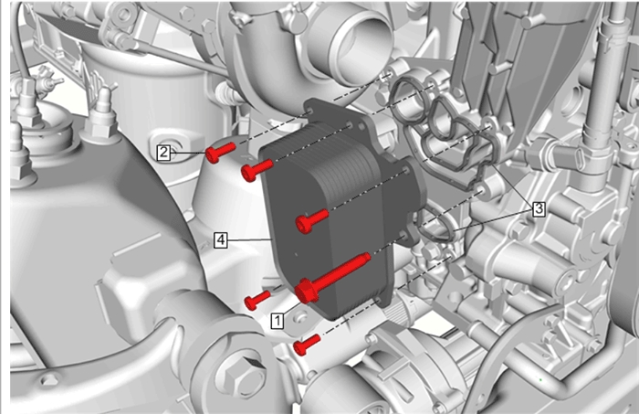
1. Engine Oil Cooler Bolt
2. Engine Oil Cooler Bolt [5X]
3. Engine Oil Cooler Seal
4. Engine Oil Cooler
dexos2 Engine Oil

Ask for and use engine oils that meet the dexos2 specification. Engine oils that have been approved by GM as meeting the dexos2 specification are marked with the dexos2 approved logo. This certification mark indicates that the oil has been approved to the dexos specification. Visit this General Motors website: https://www.gmdexos.com
Viscosity Grade
Use SAE 5W-30 viscosity grade engine oil for the 2.8L Duramax diesel engine.
Cold Temperature Operation: In an area of extreme cold, where the temperature falls below −20°F (−29°C), an SAE 0W-40 engine oil may be used. An oil of this viscosity grade will provide easier cold starting for the engine at extremely low temperatures.
Engine Oil Life System
All midsize pickup trucks feature GM’s engine oil life system, which better protects engines by recommending oil changes based on a computer software algorithm using actual engine operating conditions and can save the vehicle owner money by avoiding unnecessary oil changes.
Hydra-Matic 6L50 6-Speed Automatic Transmission — Centrifugal Pendulum Vibration Absorber
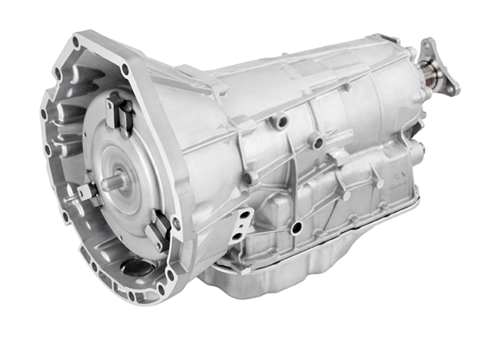
Transmission General Description
The Hydra-Matic 6L50 transmission is a fully automatic, 6 speed, rear-wheel drive, electronic-controlled transmission.
It consists primarily of a 3 element torque converter, an integral fluid pump and converter housing, a single and double planetary gear set, friction and mechanical clutch assemblies, and a hydraulic pressurization and control system.
There are four variants of the transmission, all based on torque capacity.
Architecture is common between the variants, and component differences are primarily related to size.
The 3 element torque converter contains a pump, turbine and a stator assembly.
The number of elements refers to the hydrodynamic torus arrangement within the torque converter.
The torque converter acts as a fluid coupling to smoothly transmit power from the engine to the transmission.
It also hydraulically provides additional torque multiplication when required.
Additionally within the torque converter is a pressure plate, also called the torque converter clutch, that when applied provides a mechanical direct drive coupling of the engine to the transmission.
The torque converter clutch (TCC) is applied by fluid pressure, which is controlled by a TCC pressure control (PC) solenoid.
This solenoid is part of the control solenoid valve assembly, which is located inside the automatic transmission assembly.
The solenoid is controlled through a combination of computer controlled switches and sensors.
The planetary gear sets provide the 6 forward gear ratios and reverse.
Changing gear ratios is fully automatic and is accomplished through the use of a transmission control module (TCM) located inside the transmission.
The TCM receives and monitors various electronic sensor inputs and uses this information to shift the transmission at the optimum time.
Centrifugal Pendulum Vibration Absorber
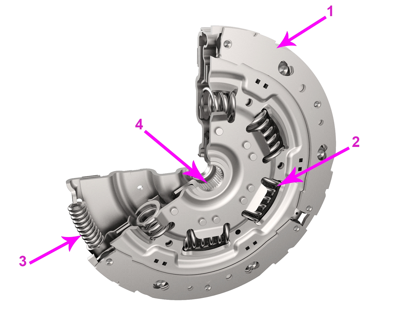
1. Pendulum masses.
2. Output isolator spring.
3. Input isolator spring.
4. Output hub.
To control vibration and noise inside the Colorado/Canyon, GM engineers integrated a device called a centrifugal pendulum vibration absorber (CPVA) in the torque converter that is used with the standard Hydra-Matic 6L50 6-speed automatic transmission.
This is the first application of a CPVA in a GM vehicle and the first time it has been used in the midsize truck segment.
The CPVA is an absorbing damper with a set of secondary spring masses, that when energized cancels out the engine’s torsional vibrations so the driver and passengers can’t feel them.
In this unique design the spring masses vibrate in the opposite direction of the torsional vibrations of the engine balancing out undesirable torsional vibrations.
Torque Converter and Integrated CPVA
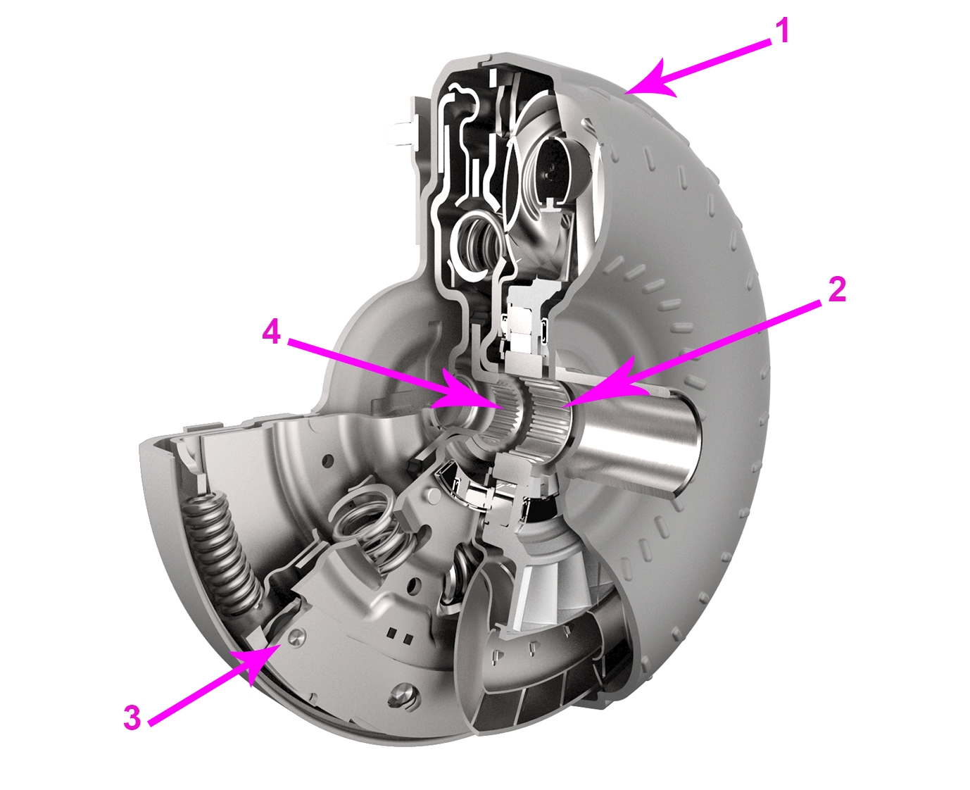
1. Torque converter assembly.
2. Torque converter transmission spline.
3. Pendulum masses.
4. Output hub.
Turbocharger System Description
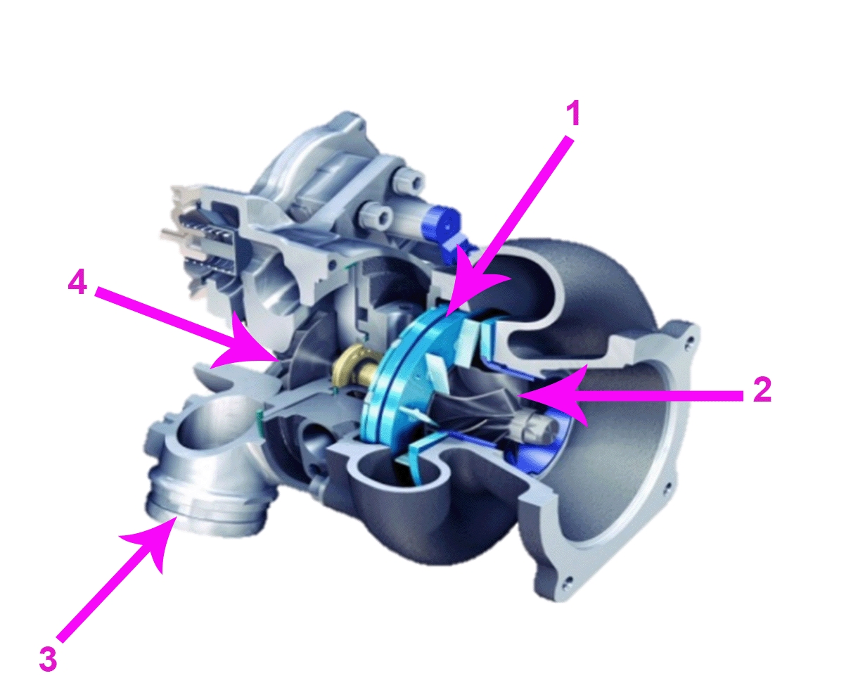
1. Vanes
2. Turbine blades
3. Turbocharger fresh air intake
4. Compressor and blades
The variable geometry turbocharger (VGT) used on the 2.8L Duramax engine is water cooled and is bolted to the exhaust manifold of the engine.
Some of the exhaust (the amount is determined by the ECM) from the engine cylinders passes through the turbine blades, causing the turbine in the turbocharger to spin.
The more exhaust that goes through the turbine blades, the faster they spin.
The turbine is connected by a shaft to the compressor, also in the turbocharger, which is located between the air filter and the intake manifold.
The compressor pressurizes and pumps the air going into the combustion chambers of the engine.
The advantage of compressing the air is that it lets the engine squeeze more air into a cylinder, and more air means that more fuel can be added at the optimal air/fuel ratio.
This produces more power from each explosion in each cylinder.
This significantly improves the power-to-weight ratio for the engine.
Throttle Inlet Absolute Pressure Sensor
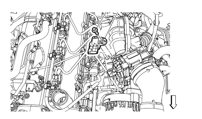
The throttle inlet absolute pressure sensor, also called a B65 intake manifold pressure and air temperature sensor, is mounted on the intake manifold and measures the intake manifold pressure and incoming air temperature.
Turbocharger Vane Position Actuator
The VGT body assembly contains a contact-less inductive VGT position sensing element that is managed by a customized integrated circuit.
The VGT position sensor is mounted within the VGT body assembly and is not serviceable.
The ECM supplies the VGT body with a 5 V reference circuit, a low reference circuit, an H-bridge motor directional control circuit, and an asynchronous signal/serial data circuit.
The asynchronous signal means communication is only going from the VGT body to the ECM. The VGT body cannot receive data from the ECM over the signal/serial data circuit.
The VGT position sensor provides a signal voltage that changes relative to VGT vanes angle.
The customized integrated circuit translates the voltage based position information into serial data using the Society of Automotive Engineers (SAE) J2716 Single Edge Nibble Transmission (SENT) protocol.
The VGT position sensor information is transmitted between the VGT body and the ECM on the signal/serial data circuit.
The ECM decodes the serial data signal and is used as voltages for VGT position sensor.
The turbocharger vanes are normally open when the engine is not under a load.
The ECM will close the turbocharger vanes to increase engine power and to create a high pressure, using boost pressure actuator.
The ECM will often close the turbocharger vanes to create back pressure to drive exhaust gas through the exhaust gas recirculation (EGR) valve as required.
At extreme cold temperatures, the ECM may close the turbocharger vanes at low load conditions in order to accelerate engine coolant heating.
The ECM may also close the turbocharger vanes under exhaust braking conditions.
Charge Air Cooler
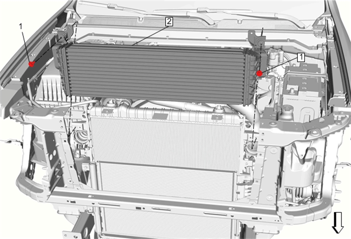
The charge air cooler (2) is located in front of the radiator. The charge air cooler is fastened in place by two bolts (1).
The outside airflow that passes through and around the fins of the charge air cooler, cools the hot compressed air within the charge air cooler that is provided from the compressor side of the turbocharger to pressurize the combustion chambers.
Engine Control Module
The ECM controls all turbocharger control functions. The ECM monitors information from various sensor inputs that include the following:
- The accelerator pedal position (APP) sensor.
- The engine coolant temperature (ECT) sensor.
- The mass air flow (MAF) sensor.
- The intake air temperature (IAT) sensor. The IAT sensor 1 is an integral part of the MAF sensor.
- The vehicle speed sensor (VSS).
- The transmission gear position or range information sensors.
- The throttle inlet absolute pressure sensor, also called the B65 intake manifold pressure and air temperature sensor.
Exhaust Aftertreatment System Description
System Overview
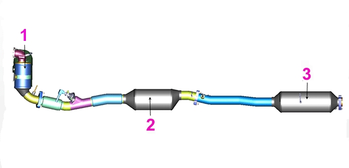
Exhaust Aftertreatment System Main Components
- Close coupled diesel oxidation catalyst (DOC) converter.
- Selective catalyst reduction (SCR) converter.
- Diesel oxidation catalyst/diesel particulate filter (DPF).
The diesel exhaust aftertreatment system is designed to reduce the levels of hydrocarbons (HC), carbon monoxide (CO), oxides of nitrogen (NOx), and particulate matter (PM) remaining in the vehicle’s exhaust gases.
Reducing these pollutants to acceptable levels is achieved through a 4 stage process as follows:
- The close coupled diesel oxidation catalyst (DOC) stage.
- The selective catalyst reduction (SCR) stage.
- The diesel oxidation catalyst (DOC) stage.
- The exhaust particulate filter (EPF) stage.
Close Coupled Diesel Oxidation Catalyst (DOC) Operation
The close coupled DOC converter (1)-main component photo), functions much like the catalytic converter used with gasoline fueled engines.
As with all catalytic converters, the DOC must be hot in order to effectively convert the exhaust HC and CO into CO2 and H20.
Selective Catalyst Reduction (SCR) Operation
While diesel engines are more fuel efficient and produce less HC and CO than gasoline engines, as a rule they generate much higher levels of NOx.
In order to meet today’s tighter NOx limits, an SCR catalyst (2)-main component photo), along with diesel exhaust fluid (DEF), also called emission reduction fluid and/or reductant, is used to convert NOx into N2, CO2, and H2O.
Diesel Oxidation Catalyst (DOC) Operation
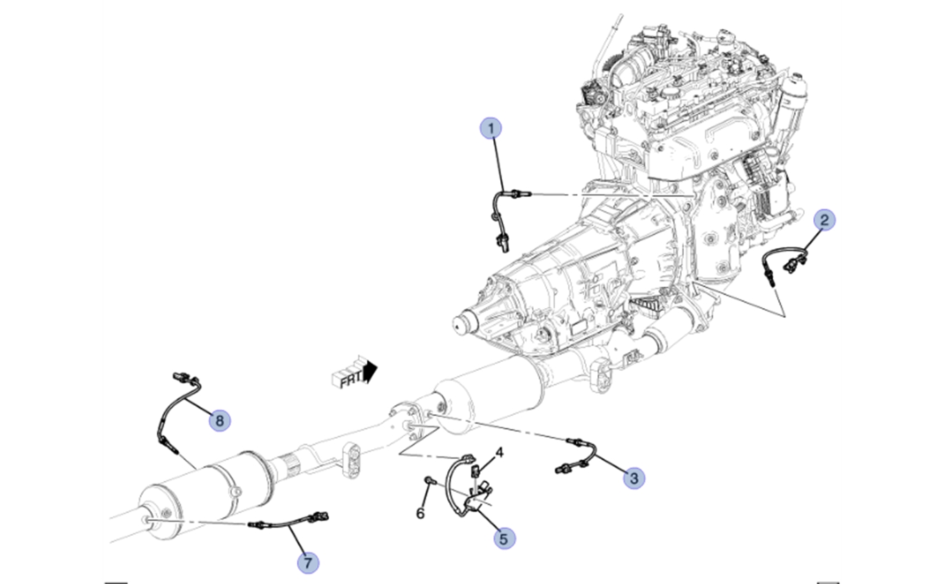
The diesel oxidation catalyst (DOC) (3)-main component photo), has two functions.
In addition to reducing emissions, the DOC also generates the exhaust heat needed by the DOC stage.
Exhaust gas temperature sensors (7,8) are located upstream and downstream of the DOC.
By monitoring the temperature differential between these two sensors, the ECM is able to confirm DOC light-off. Light-off is confirmed by a DOC output temperature that is greater than its input temperature.
In order to generate the high exhaust temperatures needed for regeneration, the aftertreatment system increases exhaust temperatures by using the low pressure diesel hydrocarbon injector (5), also called a Q67 exhaust aftertreatment fuel injector, to inject diesel fuel into the exhaust gases prior to entering the DOC. The added fuel is not combusted but is oxidized by the DOC to create heat.
NOx Sensors
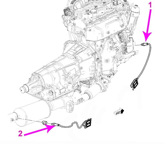
The ECM uses two smart NOx sensors to control exhaust NOx levels.
The first NOx sensor (1) is located at the turbocharger outlet and monitors the engine out NOx.
The second NOx sensor (2) is located in the exhaust pipe downstream of the SCR (2)-main component photo), and monitors NOx levels exiting the SCR.
The smart NOx sensors communicate with the ECM over the serial data line.
The NOx sensors incorporate an electric heater to quickly bring the sensors to operating temperature.
As moisture remaining in the exhaust pipe could interfere with sensor operation, the ECM delays turning on the heaters until the exhaust temperature exceeds a calibrated value.
This allows any moisture remaining in the exhaust pipe to boil off before it can effect NOx sensor operation.
Depending on engine temperature at start up, the delay can be less than a minute or as long as two minutes.
Typically, NOx sensor 1 will reach operating temperature faster than NOx sensor 2 as it’s closer to the engine’s hot exhaust.
At idle or low engine speeds, NOx sensor 2 may require up to five minutes to reach operating temperature.
The sensors must be hot before accurate exhaust NOx readings are available to the ECM.
Exhaust Gas Temperature (EGT) Sensors — Position 1, Position 2, Position 3

The engine uses exhaust gas temperature management to maintain the SCR catalyst (2)-main component photo), within the optimum NOx conversion temperature range of 390–750°F (200–400°C).
The ECM monitors two EGT sensors (1 and 2) located upstream and one EGT sensor (3) located downstream of the SCR in order to determine if the SCR catalyst is within the temperature range where maximum NOx conversion occurs.
Exhaust Gas Temperature Sensors — Position 4, Position 5
The ECM uses two EGT sensors (7 and 8) to measure the temperature of the exhaust gases at the inlet and outlet of the exhaust Particulate filter (EPF) integrated within the DOC (3)-main component photo).
The EGT sensors are variable resistors. When the EGT sensors are cold, the sensor resistance is low, and as the temperature increases, the sensor resistance increases.
When sensor resistance is high, the ECM detects a high voltage on the signal circuit. When sensor resistance is low, the ECM detects a lower voltage on the signal circuit.
Proper exhaust gas temperatures at the inlet and outlet of the EPF are crucial for proper operation and for initiating the regeneration process.
A temperature that is too high in the EPF will cause the EPF substrate to melt or crack.
Emission Reduction Fluid Injector
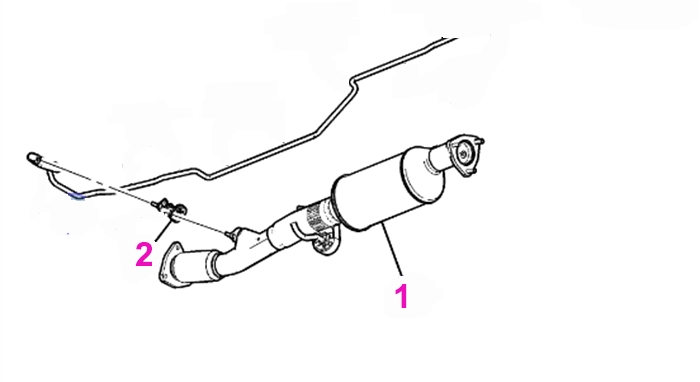
Diesel exhaust fluid (DEF), also called emission reduction fluid and/or reductant, is injected into the exhaust gases prior to entering the SCR (1).
This is accomplished by using the emission reduction fluid injector (2) that is mounted in the exhaust system prior to the SCR.
Within the SCR, NOx is converted to nitrogen (N2), carbon dioxide (CO2) , and water vapor (H20) through a catalytic reduction fueled by the injected reductant as part of the process to reduce the amount of regulated emissions that are produced.
DEF or reductant is a mixture of deionized water and urea.
Reductant Reservoir
The on-board reductant reservoir holds approximately 5 gallons (19 liters) of reductant.
An ECM controlled pump within the reservoir supplies pressurized reductant through a supply pipe to the emission reduction fluid injector (2).
Diesel Particulate Filter (DPF)/Exhaust Particulate Filter (EPF)
The system has a diesel particulate filter (DPF) also called an exhaust particulate filter (EPF), integrated within the DOC (3)-main component photo), as part of the exhaust aftertreatment system to reduce vehicle emissions.
The EPF captures diesel exhaust gas particulates, also known as soot, preventing their release into the atmosphere.
This is accomplished by forcing particulate-laden exhaust through a filter substrate of porous cells, which removes the particulates from the exhaust gas.
The exhaust gas enters the filter, but because every other cell of the filter is capped at the opposite end, the exhaust particulates cannot exit the cell.
Instead, the exhaust gas passes through the porous walls of the cell leaving the particulates trapped on the cell wall.
The cleaned exhaust gas exits the filter through the adjacent cell.
The EPF is capable of reducing more than 90 percent of particulate matter during this process.
Differential Pressure Sensor
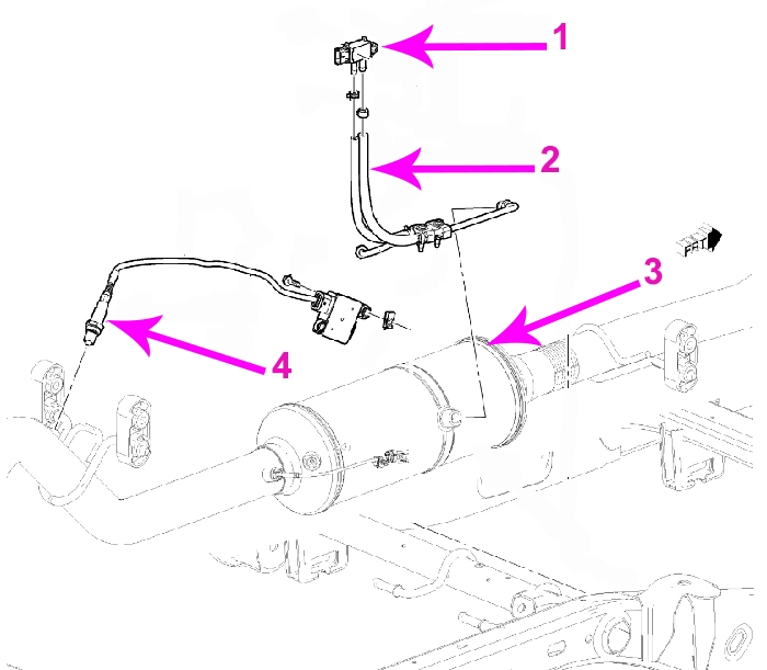
Pressure connections provided by the pipes (2) for the differential pressure sensor (DPS) (1) at the inlet and outlet of the exhaust particulate filter (EPF) (3) allow the DPS to measure the exhaust pressure drop across the EPF.
This pressure drop increases as trapped soot collects in the cells of the EPF during engine operation.
The rate at which soot collects varies with the power demands placed on the engine.
There are two sensing elements in the DPS, one for the upstream side of the DPF, and the other for the downstream side.
Pressure from each side of the EPF is applied to the bottom side of a silicon diaphragm in each sensing element.
Atmospheric pressure is applied to the top side of each diaphragm.
The relative pressure differences in each sensing element are converted to a voltage.
The difference in these two voltages is sent to the ECM.
As the EPF becomes clogged or restricted, the pressure on the upstream side increases because of back pressure due to the restriction of the exhaust gas flow through the EPF.
When the exhaust pressure difference has increased above a calibrated threshold, a high particulate loading condition is indicated and the ECM will command a regeneration event in order to restore the filter.
Exhaust Particulate Sensor/Particulate Matter (PM) Sensor

The exhaust particulate sensor (4), also called the particulate matter (PM) sensor, determines the amount of particulates or soot remaining in the diesel exhaust gas exiting the tailpipe by monitoring the collection efficiency of the EPF and to aid in emission diagnostics.
The PM sensor is similar to a heated oxygen sensor with a ceramic element but also includes an individually calibrated control unit.
The PM sensor sensing element includes two comb-shaped inter-digital electrodes, a heater and a positive temperature coefficient (PTC) resistor for temperature measurement.
The operation of the PM sensor is based on the electrical conductivity characteristic of the soot.
As the exhaust gas flows over the sensing element, soot is absorbed in the combs between the electrodes, eventually creating a conductive path.
When the path is formed, it generates a current based on the voltage being applied to the element.
The measurement process continues until a preset current value is reached.
To avoid misleading readings, the sensor operates on a “regenerative” principle, where the soot is cleaned off by heating up the element to burn off the carbon, before the measurement phase begins.
The amount of regenerations is based on vehicle strategy and when the amount of regenerations is reached, the cumulative current readings are used to determine the amount of soot concentration in the exhaust gas, and thus the collection efficiency of the EPF.
Exhaust Tailpipe and Cooler
The exhaust aftertreatment system requires a unique exhaust tailpipe with an exhaust cooler.
The exhaust cooler mixes air with the exhaust to lower the temperature before it leaves the tailpipe.
The DOC (3)-main component photo), integrated EPF, the tailpipe, and any other exhaust system components must not be altered.
Intake Air (IA) Valve
The intake air (IA) valve is located upstream of the intake air heater, and is normally in the open position.
The ECM commands the valve to close in order to precisely control combustion temperature during DPF regeneration.
The IA valve will ensure the temperature of the exhaust gas remains in an efficient range under all operating conditions.
The IA valve system uses a position sensor located within the valve assembly to monitor the position of the valve.
The IA valve uses a motor to move the valve to a closed position and spring tension returns it to the open position.
The motor is operated through Motor Control 1 and Motor Control 2 circuits.
Ash Loading
Ash is a non-combustible by product from normal oil consumption.
Low ash content engine oil is required for vehicles with the exhaust particulate filter system.
Ash accumulation in the EPF will eventually cause a restriction in the particulate filter.
Regeneration will not burn off the ash, only particulate matter is burned off.
An ash loaded EPF will need to be removed from the vehicle and cleaned or replaced.
Diesel Exhaust Fluid (DEF)
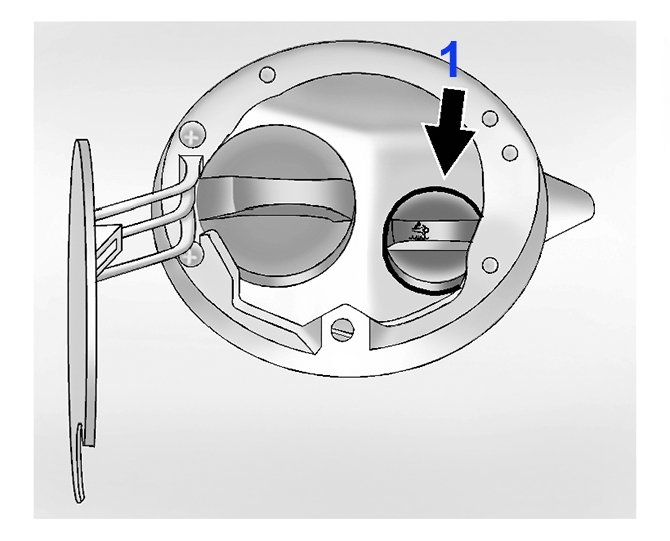
Diesel exhaust fluid (DEF), also called emission reduction fluid and/or reductant is used with diesel engines to reduce the amount of regulated emissions that are produced.
The fluid level in the DEF tank must be maintained for the vehicle to run correctly.
The DEF canister (tank) is mounted out of sight beneath the bed and should last approximately 7,500 miles (12,070 km) under normal use.
The DEF fill cap is next to the diesel fuel fill cap behind the vehicle fuel fill door. The DEF fill cap (1) is blue and the diesel fuel fill cap is green.
Do not overfill the DEF tank. When fluid reaches the top of the DEF fill pipe, stop filling.
If you spill DEF on the vehicle while filling the tank, rinse the area with water and wipe the surface with a damp cloth.
DEF is not a fuel additive. DEF should not be mixed with or added to diesel fuel.
DEF freezes when exposed to temperatures below 12°F (−11°C). This is normal.
Use only DEF that is GM approved. DEF can be purchased at a Chevrolet or GMC dealer or at diesel truck stops.
Regeneration
Normal Regeneration
Regeneration is the process of removing the captured particulates through incineration within the EPF.
Elevated temperatures are created in the DOC (3)-main component photo), through a calibrated strategy in the engine control system.
Regeneration occurs when the ECM calculates that the particulate level in the filter has reached a calibrated threshold using a number of different factors, including engine run time, distance traveled, fuel used since the last regeneration, and the exhaust differential pressure.
In general, the vehicle will need to be operating continuously at speeds above 30 mph (48 km/h) for approximately 20-30 minutes for a full and effective regeneration to complete.
During regeneration the exhaust gases reach temperatures above 1,022°F (550°C). The ECM monitors the EGT sensors during regeneration.
If the sensors indicate that regeneration temperatures are exceeding a calibrated threshold, regeneration will be temporally suspended until the sensors return to a normal temperature.
If EGT temperatures fall below a normal calibrated threshold, regeneration will be terminated and a corresponding DTC should set.
If a regeneration event is interrupted for any reason, it will continue, including the next key cycle, when the conditions are met for regeneration enablement.
Normal regeneration is transparent to the customer.
The self-cleaning occurs approximately once per tank of fuel.
Service Regeneration
A scan tool is an essential tool that is required for service regeneration.
Commanding a service regeneration is accomplished using the scan tool output control function.
The vehicle will need to be parked outside the facility and away from nearby objects, such as other vehicles and buildings, due to the elevated exhaust gas temperature at the tail pipe during regeneration.
The service regeneration can be terminated by applying the brake pedal, commanding service regeneration OFF using the scan tool, or disconnecting the scan tool from the vehicle.
Regeneration Process
A number of engine components are required to function together for the regeneration process to be performed.
These components are the fuel injectors, turbocharger, IA valve, fuel pressure control, and the intake air heater (IAH).
The regeneration process consists of several stages: Warming up the DOC to 662°F (350°C) by performing the following:
- Reducing air flow with the intake air valve
- Increasing or decreasing boost pressure with the turbocharger, depending on engine load
- Elevating the engine speed
- Reduce fuel rail pressure
- Retard fuel injection timing

- Add fuel using the low pressure diesel hydrocarbon injector, also called a Q67 exhaust aftertreatment fuel injector (5), that is mounted in the exhaust prior to the DOC/exhaust particulate filter (3)-main component photo). The added fuel is not combusted but is oxidized by the DOC to create heat.
Cleaning Exhaust Filter Messages
Cleaning Exhaust Filter Continue Driving This message will appear on the DIC when an exhaust particulate filter cleaning is required. To clean the filter, drive the vehicle above 30 mph (50 km/h) until the warning message goes OFF. This will take about 30 minutes.
Cleaning Exhaust Filter Must Continue Driving It is important to keep driving to clean the exhaust filter. This will take about 30 minutes.
Tow/Haul Mode

If equipped, Tow/Haul Mode adjusts the transmission shift pattern to reduce shift cycling.
This provides increased performance, vehicle control, and transmission cooling when driving down steep hills, mountain grades, towing, or hauling heavy loads.
Turn the Tow/Haul Mode ON and OFF by pressing the button on the center stack. When the Tow/Haul Mode is activated, a light on the instrument cluster will illuminate.
Pressing the Tow/Haul mode button activates the diesel exhaust brake system simultaneously.
Exhaust Brake
The integrated driver selectable exhaust brake system is based on the system introduced on the 2015 Silverado HD and Sierra HD models.
It is a smart system that varies the amount of brakes needed for the vehicle, load and grade.
The engagement of the system is smooth and quiet.
The system uses the compression power of the 2.8L Duramax engine to control vehicle speed and reduce brake pad wear.
When the exhaust brake is engaged in cruise mode, exhaust cruise grade braking will help the cruise control system maintain the desired vehicle speed when travelling downhill, keeping the driver from having to apply the brakes and exit cruise control to maintain the selected speed.
When the exhaust brake is engaged in non-cruise mode, the transmission and the exhaust brake deliver the correct amount of braking to assist in vehicle control, regardless of vehicle load.
The exhaust brake only activates when the transmission torque converter is locked. This can vary based on vehicle speed, gear, and load.
Vehicle High Strength Steel Structure
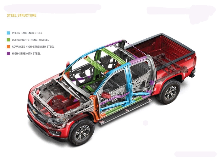
- Light Blue: Press Hardened Steel.
- Light Green: Ultra High-Strength Steel.
- Orange: Advanced High-Strength Steel.
- Purple: High-Strength Steel.
Fully boxed frames formed primarily from high-strength steel reduce weight and increase stiffness for a quieter ride and better handling.
Key areas of the body structure also benefit from high-strength steels, reducing mass and enhancing strength and safety.
Overall, about 71 percent of the body structure is comprised of high-strength steels.
The pickup box consists of roll-formed steel, which is lighter and stronger than traditional stamped steel.
Auxiliary Electric Heater
The Colorado/Canyon equipped with the 2.8L Duramax diesel are also equipped with an auxiliary electric heater grid to provide faster cabin warm-ups in cold climates.
The auxiliary heater grid is mounted in the low-center of the HVAC module, where heat is transferred from the grid to air which is directed to the floor outlet ducts.
The auxiliary heater is enabled only when the cabin temperature is set to MAX, the engine coolant temperature is less than 176°F (80°C), and the outside air temperature is less than 54°F (12°C).
When the engine coolant temperature rises above 176°F (80°C), the temperature control is moved away from the MAX position, or the outside air temperature is above 54°F (12°C), the auxiliary electric heater is disabled, and cabin heat is managed only by the coolant based heater core and temperature door position.
If the auxiliary electric heater is activated and then turns OFF, it can actuate once again if the engine coolant temperature drops below 167°F (75°C), or the outside air temperature drops below 46°F (8°C).
OnStar 4G LTE
The built-in OnStar Wi-Fi hotspot available in Chevrolet and GMC vehicles supports up to seven mobile devices so passengers can connect to the content they want.
OnStar with 4G LTE offers a strong, more reliable signal; and it’s built-in, so it’s easy to use.
Plus, it’s connected to your vehicle battery, so you’re always fully charged for the adventure ahead.
The powerful OnStar connection also enables improved access to existing OnStar safety and security services, including the ability to transmit voice and data simultaneously.
That means OnStar advisors can run a diagnostic check without ever leaving the call, making customer interactions quicker and more seamless.
It’s the most comprehensive in-vehicle safety and connectivity system available.
Special Tools
The following new tools were released specifically to service the 2.8L Duramax diesel engine:
| Tool # | Description |
| EN-51265 | Crankshaft Sprocket Holder |
| EN-50025 | Locking Tool, Fuel Pump & Timing Belt Sprockets |
| EN-50026 | Installer, Rear Main Seal |
| EN-50031 | Adapter, Compressor, Valve Spring (Head Off) |
| EN-50034 | Guide Pins, Connecting Rod |
| EN-50718 | Installer, Front Crankshaft Seal |
| EN-50723 | Valve Stem Seal Installer |
| EN-51025 | Camshaft Timing Tool |
| EN-51104 | HP Fuel Pump Sprocket Locking Tool |
| EN-51110 | Compression Gauge Adapter |
| EN-51162 | Balance Shaft Backlash Adapter |
dexos® is a Registered Trademark of General Motors LLC
LLC
dexos2™ is a Trademark of General Motors LLC
LLC
Duralife™ is a Trademark of General Motors LLC
LLC
Duramax™ is a Trademark of General Motors LLC
LLC
Duramax® is a Registered Trademark of General Motors LLC (in the United States)
Hydra-Matic™ is a Trademark of General Motors LLC
LLC
OnStar® is a Registered Trademark of OnStar LLC
SEOCONTENT-END
Bulletin No.: PI1539
Date: Oct-2015
To View or Download this Document Click Here
 Loading...
| “This site contains affiliate links for which OEMDTC may be compensated” |
- Prime Guard DEF is a safe, environmentally friendly solution for Selective Catalytic Reduction
- Blue Def DEF002-2PK Diesel Exhaust Fluid, 2.5 Gallon, 2 Pack
- DEF Fluid Pallet - Premium BlueDEF Fluid 40 Cases - BlueDEF Diesel Exhaust Fluid 2.5 Gallon Case - Pack of 40 BlueDEF Jugs and 1 Pack of Heavy Duty Wipes
- America's #1 brand of Diesel Exhaust Fluid Conforms to the ISO-22241-1 specification for DEF, and is an American Petroleum Institute (API) certified diesel exhaust fluid
- BlueDEF's Purity Guarantee is our assurance the DEF your are purchasing has been tested to meet or exceed the strictest OEM standards
- [𝗙𝗜𝗧𝗦] - Compatible with Land Rover Discovery 5, Range Rover Sport, Range Rover Full Size L405, Range Rover Velar, and Range Rover Evoque, diesel vehicles only (see exact model years below). Also is OE spec for other makes as noted.
- [𝗟𝗘𝗔𝗞-𝗙𝗥𝗘𝗘] - Each bottle is topped with a special cap and neck sheath designed for screw-in use on the DEF fill port of BMW and other vehicles, meaning leak-free and mess-free filling on vehicles with screw-in style DEF fill ports.
- [𝗢𝗘𝗠-𝗤𝗨𝗔𝗟𝗜𝗧𝗬] - Original Equipment Diesel Exhaust Fluid (DEF) 83190441139 made in Germany by AdBlue. This This SCR diesel exhaust NOx-reducing aqueous urea solution complies to ISO specification ISO 22241-1.
- [𝗖𝗢𝗡𝗩𝗘𝗡𝗜𝗘𝗡𝗧] - 2 gallons fluid in (4) half-gallon size bottles (7.57-liters / 256oz total), providing ample fluid for regular replacement.
- [𝗢𝗘-𝗥𝗘𝗙𝗘𝗥𝗘𝗡𝗖𝗘] - Meets OE Specifications / Compatible with: BMW 83190441139, Land Rover LR072258, Jaguar T4N 12112, Mercedes-Benz A 000 583 0107, VW / Audi G 052 910 A2, Mazda 0000-AD-002, Peugeot / Citroen 1611328380.
- Meets GM Original Equipment specifications to be approved for use in GM vehicles as well as in non-GM diesel vehicles that have an SCR (Selective Catalytic Reduction) system to meet regulated NOx emissions (Based on EPA certification testing. Your actual emissions will vary based on several factors including temperature, terrain, and driving conditions).
- High quality formula is made from high purity urea and deionized water.
- Meets API regulations and ISO 22241 standard for purity and concentration
- Nozzles sold separately
- One gallon of BlueDEF is used approximately every 300 miles
- A truck with a 20 gallon DEF tank can go up to 6000 miles between fill-ups
- When used in an SCR system BlueDEF will reduce the levels of NOx emissions of those engines
- Non-flammable
- Diesel exhaust fluid
- Required for diesel vehicles equipped with a selective catalytic reduction (SCR) emissions after treatment system
- Reduces NOx emissions in diesel vehicles with an SCR catalyst
- AUS32 fluid meeting all the requirements and purity standards of ISO 22241 and DIN70071
- Nozzle specifically designed to fit the DEF filler opening of 2011MY and forward Ford
 diesel vehicles (as well as many competitive vehicles) and prevent over filling the DEF tank
 - Use only dispensing systems that are compatible with DEF
- 80 - 2.5 Gallon Boxes of DEF
- Dispensing nozzle for easy pouring
- Meets or exceeds all EPA standards
- Meets the stringent AUS 32, DIN 70070, ISO 22241 purity and concentration standards
- The product can be used without removing from the box
Last update on 2025-05-08 / Affiliate links / Images from Amazon Product Advertising API
This product presentation was made with AAWP plugin.


